
3D Prints, Product Design
Process Drives Product Design Creativity, Part 3
Jul
The ideation phase of product design is too often glorified. You’ve seen it — the beautiful sketches, the compelling imagery — the fake stuff. Don’t get me wrong, this is a fun and important stage, but a pretty sketch is meaningless if not supported by logical, critical, and thorough analysis. That kind of analysis — that’s what I do! For more on the work leading up to this point, please review part 1 and part 2 of this series. We ended part 2 with a definition of our product. Now we embark on a three-pronged process of ideation, design, and prototyping.
We will design and prototype a planter consisting of a hard vessel using a removable filter (in place of rocks) and an integrated drain. The planter will use changes in mass to signal “time to water” with an indicator.
Design
Now we design a first draft of our product. This isn’t going to be the be all end all, instead, this is the model that will test the basic principles of our concept.
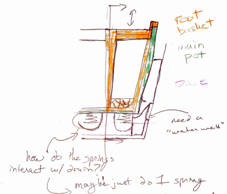
First, determine the necessary components of the design and write it all down. When I get an idea down on paper, I almost always come away with something better than what was in my head. Here are some snippets from my notebook.
Wait, this is basically a finished design, where did it come from? When did I decide to use a compression spring?
Cutting Corners
That’s right, I’m cutting some corners. I could excuse it by saying that this is just a prototype, blah, blah, but the truth is that I have a mechanical design more or less in my head that I want to implement. Once we selected our concepts from the morphological chart in part two, I knew what I was going to make. Sometimes this happens. It can be a problem.
It is likely that there is a better solution than this one. I won’t uncover it because I’m skipping opportunities for design and analysis. On the flip side: we need to get this thing done! I want to test the basic principles and then use the thing and see if I like it. If I like it, then I can go back and explore the missed opportunities. If I don’t like it, or if I’m the only one, then this is good enough!
What is important, though, is that we are intentional in our corner cutting. I want to be able to look back and quickly see those corners. For me that happens two ways: one, physically marking a relevant page and making a note in my notebook; and two, maintaining a list of assumptions and corners cut. OK, now that I have appropriately excused any shortcuts you may notice…let’s get back to it!
The System
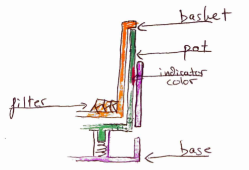
While I’m making the sketches shown above I’m concurrently identifying, naming, and defining the parts of the system. Once I have a good grasp on what parts are involved I make a list of them and their necessary functions. Let’s do it here.
Basket:
- Contains filter
- Allows plant to be easily removed
- Fits tight against pot
- Does not move in operation
- Could be rigid or flexible
Pot:
- Fits tight against basket
- Supports basket
- Allows water to flow out through bottom
- Engages with spring
- Reveals indicator
- Moves up and down with changes in mass
- Can be removed entirely, but only intentionally
Base:
- Retains spring
- Acts as bearing surface for pot
- Contains drained water
- Has water feature
At this point in the design questions come up. We know that the plant sits in the Basket/Pot assembly and the whole things moves up and down using the force of a spring. How much does it need to move? What exactly is the signal? How much will the mass change from water loss?
The first question to answer is the latter: how much will the mass of the pot assembly change with moisture loss? To answer this, I use the internet. A quick search for something like “weight of wet potting soil” will quickly get you the information you need. I ran the numbers for 4″ and 6″ pots and found that for a 4″ pot I should plan to detect a change of somewhere between .3 and 1.5 pounds. That’s a big range, so I did a little testing.
At the time I had four starts (basil, mint, lavender, and tomato) that had been sitting out for a couple of days. They were dry and needed water! I took their mass before and after watering, and I found that for a 2″ pot the change in mass between dry and fully saturated was between .15 and .41 pounds with an average of .3lb. Thus, for a 4″ pot (4X the volume) I should expect a change of about 1-2lb, average of about 1.2lb.
Now that we know our change in mass: how precise do we need to be? How much travel do we need for our specified weight range? Can we find a spring that can do it?
I started with a reasonable estimate of the amount of travel needed: somewhere between 1″ and 2.5″ of spring travel in the trigger range. That leads me to a spring constant of around 1 in/lb. Well, turns out a spring with that much travel and that light a spring constant is hard to find! McMaster had nothing, but I found a likely candidate on Century: spring 12420.
Great, next: what is the signal? And what does this thing look like?
Let’s start with the signal.
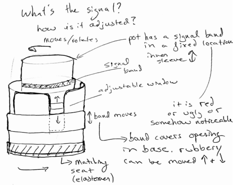 I started this sketch thinking that I could have a signal band on the pot that moved up and down. The position of the band relative to the window on the base would be your indicator. Then I thought, what if the window were adjustable instead? Well, to do that, all you need to do is put a band on the outside and make the signal feature on the pot fixed. Good enough!
Concept Sketches
It’s very common to make an underlay as a sketch aid. Underlays provide a framework for your sketch, letting even poor sketchers like myself communicate a concept. To start, I modeled the system components roughly (as cylinders). Here’s a screenshot from Fusion 360 of the mock-up parts plus a couple 3D printed vases (one is self watering) that I imported for reference.
I took screenshots of line-representations and threw them into a word document to make underlays. They look like this:
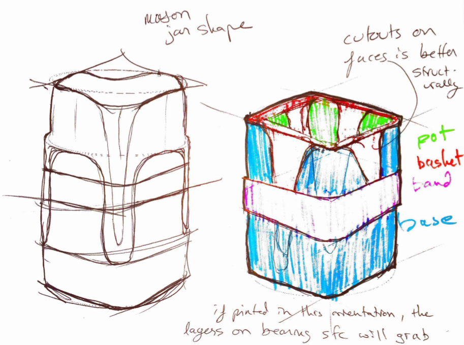
 The left image is the trigger point and the right is fully saturated. Now I have something that I can use to guide my concept sketches! Before we move ahead…be warned: sketching concepts is not one of my strengths. This is when I most often partner with an industrial designer or two. Here are some highlights from my sketches…
This one, above — just no.
Names are important: let’s call this one Hot Rod. Hot Rod really appeals to me on a mechanical design level. There’s the opportunity here to design a perfectly constrained mechanism! I modeled it quickly in CAD, though, and found it visually awkward with no obvious fix. Check out the models, below. I actually got the design all the way to “ready to print” but just couldn’t tolerate how it looked. Here’s a screenshot from my working environment (how I see it while I’m modeling) plus a quick render.
Ugly, right? Let me know if you have any ideas about how to make this approach more attractive. I know there is a good solution! Make note: this would be the fastest way to test the concept. Rubber band, spring, two bic pens, and two printed parts.
Next up, our winner!
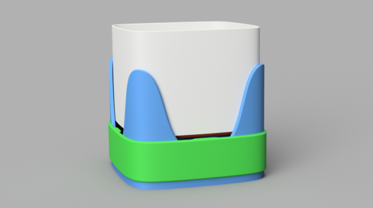
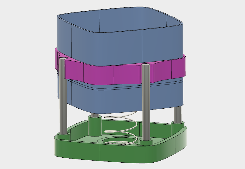
 Let’s call this one the Maesprung Planter (Mason + Sprung). The Maesprung uses the same basic principles as Hot Rod, but does it in a way that is visually simplified. It’s also a little less mechanically compelling, but that’s OK. I quickly mocked this up in CAD to help visualize the concept.
CAD Design
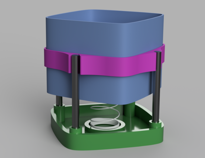
We already have a solid start on the CAD design. I often work in CAD while I’m deciding between concepts. With the work we’ve done, finishing the 3D model is a fairly quick job. After about 4 hours of work I had parts ready to print. Let’s take a look at some screenshots.
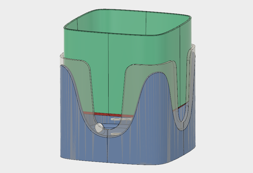
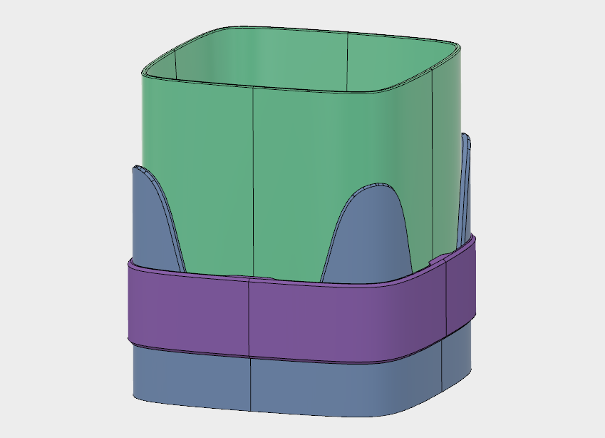

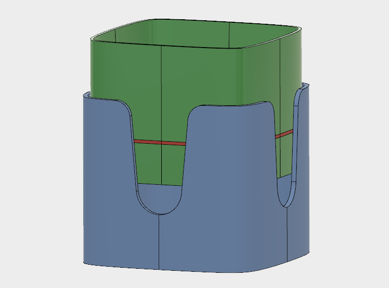
As I designed the model aspects and features of the product came and went. For example, I designed a coaster and a cap to be printed in the same elastomer as the band, but the cap was too much, and the coaster seemed awkward and was certainly not necessary to test the product. I’ve also abandoned the root basket part, choosing instead to pot the plant simply in the pot. We can set aside the root basket for a product enhancement down the road.
Print, Prototype, and Plant!
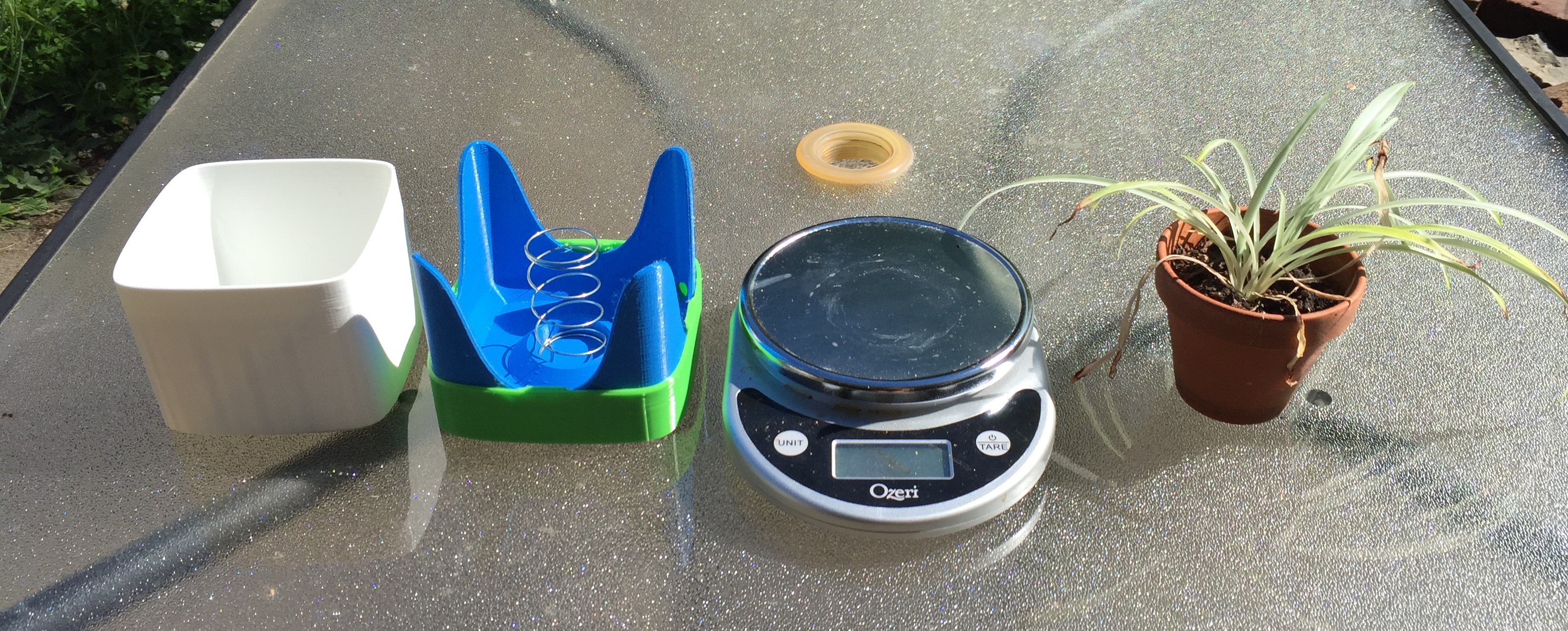
 Here’s our planter! Next: print the three parts, add plants and dirt, water, and see what happens. I chose a much neglected spider plant to be our test subject. It was bone dry!
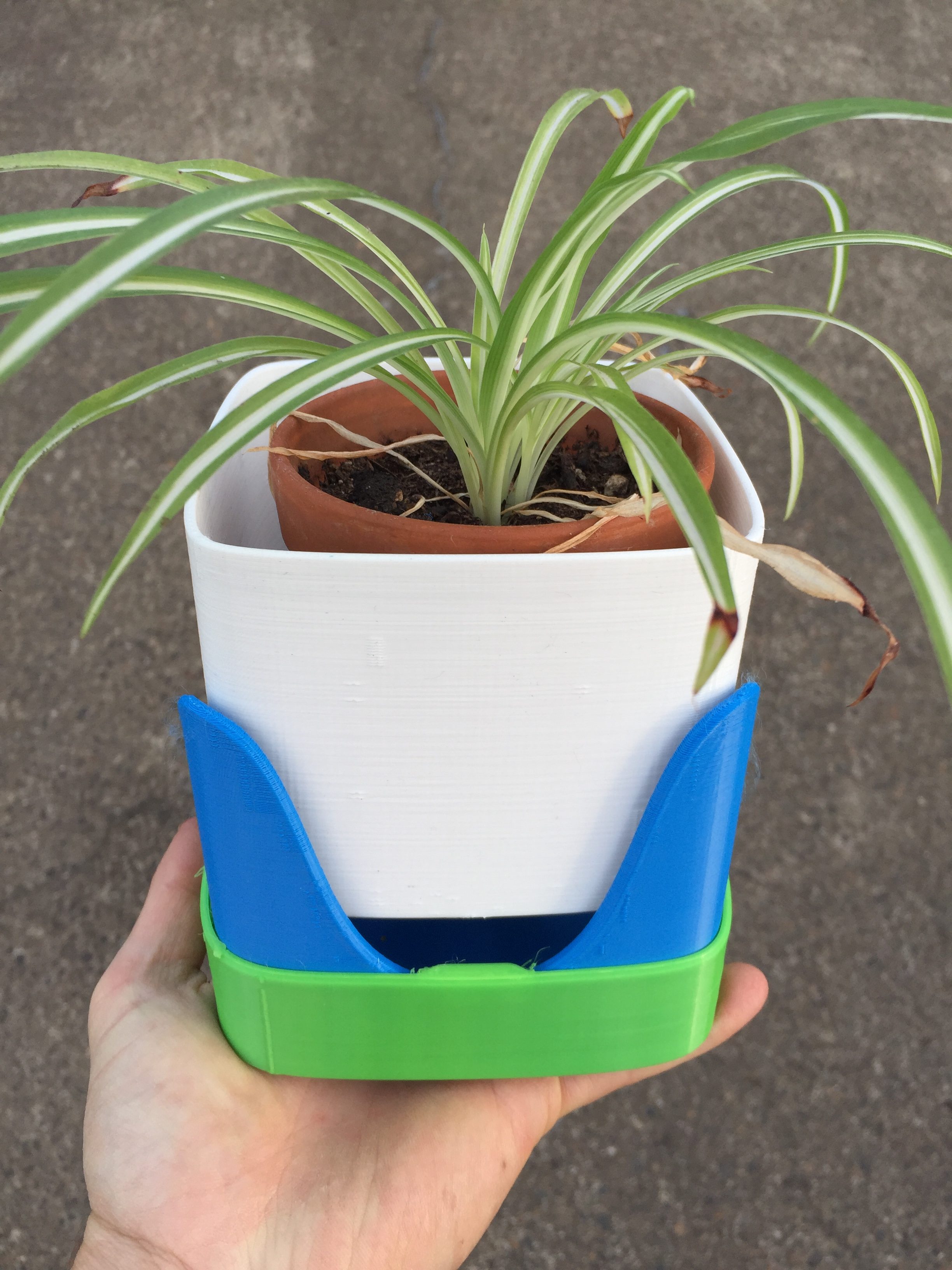
I measured the weight of the plant/pot once potted (but dry) and again after watering. Dry: 1.45 pounds. Saturated: 1.96 pounds. So almost exactly a half pound difference between bone dry and saturated. It seems like we might want to water again at about 0.1-0.2lb heavier than dry. Here’s about how high that is:
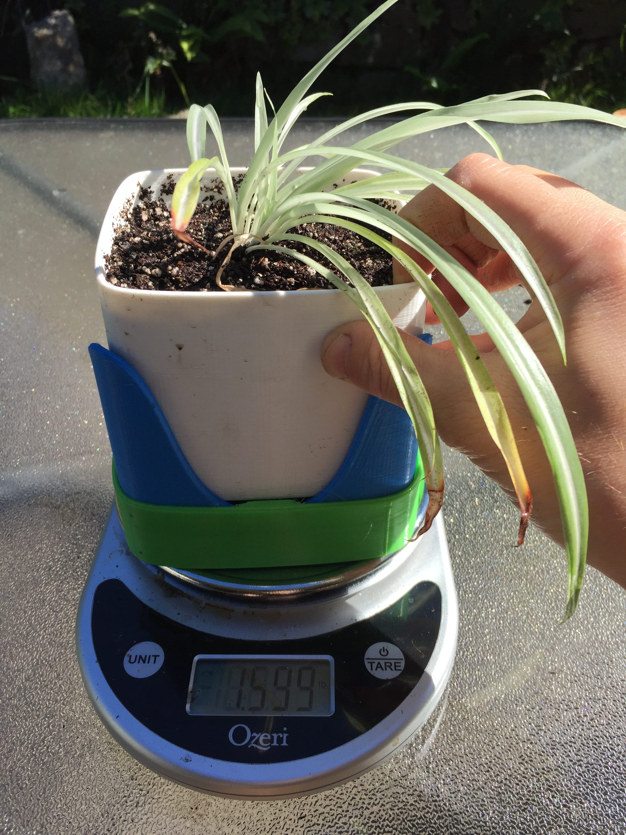
So we can see that we’ll want to have the band slammed all the way down on the base if we want to use the bottom of the pot as the trigger level. That’s lower than I was expecting. In the next version I may have a color change on the pot to serve as an indicator. Then I can have the band sit higher on the base.

OK, we got this thing printed, planted and ready to go. But we forgot to ask an important question:
What do we need to learn from our prototype?
Here’s what I did with the prototype.