
EEV Arrow is a headless 3D printed electric violin with custom barrel tuners and the option to use some sweet magnetic pickups.
ATTENTION
You must use Pods R5 or later.
Earlier versions have failed under load and can send bits of plastic flying at high speed.
This design is highly experimental and pushes the limits of the materials. Use at your own risk, and pay close attention to your instrument.
If one string loses tension, but others do not, you likely have a pod failure.
Protect your eyes, loosen that string carefully, and remove and inspect the pod.
Here you’ll find all the documentation you need to build your own EEV Arrow, including step-by-step assembly instructions.
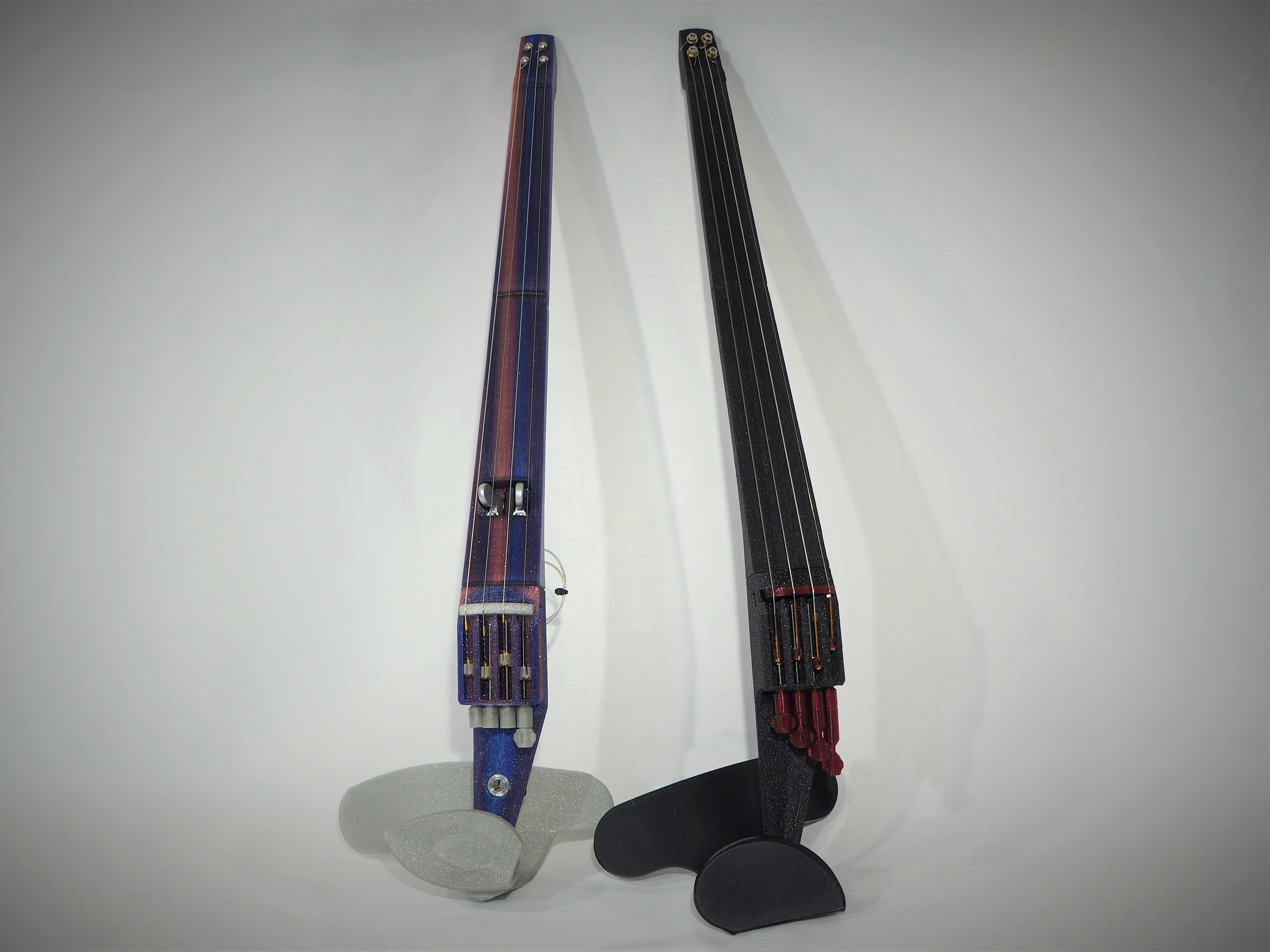 EEV Arrow is the F-F-Fiddle evolved.
The F-F-Fiddle, published in 2014, was the first freely available 3D printed electric violin. It led to so many interesting violins! One maker in the Netherlands had a specific vision for how he would like the F-F-Fiddle to evolve. He commissioned this design update in early 2021 and we worked in collaboration during development. Thank you!
EEV is short for Extruded Electric Violin, and Arrow was a nickname for one of the sketched concepts.
Currently the design and print files are available by request. Please contact us.
You can buy a kit of parts here.
This design is licensed CC-BY. You may remix and distribute (or not) to your heart’s content. Credit OpenFab PDX and link to this page when possible. You may use this design for commercial use.
This page has the most up-to-date build instructions, parts lists, and project info. Content here will be updated as needed for future changes.
The best way to build an EEV Arrow is to purchase a kit. We use a lot of uncommon hardware in the build, plus your kit purchase supports the work!
If you haven’t yet, go check out the Google Group. There is also a Discord Server full of conversation and problem-solving. Discord is the best place to get help with your build. You may also shoot us an email anytime through the contact page.
Acknowledgements
EEV Arrow was developed in conversation with several folks on the OpenFab Violins Discord server. One of them developed a similar instrument and is making some excellent electric violins, violas, and 5-string fiddles. Check them out on 3d-strings.ch!
EEV Arrow uses a technique for securing the loose ends of the strings that was blogged by guitar maker Mike Sankey at Sankey Guitars. Here’s the blog post he wrote. Thank you, Mike!
Frequently Asked Questions
Right now I only recommend using Oleg’s magnetic pickups! There is some issue with the piezo disk (K&K Twin Spot) setup and they are not giving decent sound.
About Oleg Shevchuk’s magnetic pickups: these innovative magnetic pickups provide excellent sound, a strong signal, and completely isolate the amplified sound from any noise against the body (like fingers tapping the fingerboard). These pickups are available in our purchased kits, or you can order directly from Oleg. Contact him via his Instagram page: @oleg_shevchuk_violin
Want to experiment? EEV Arrow parts are designed to accept K&K Twin Spot or Violinissimo pickups, but I have not gotten these to work well yet. You may purchase a ‘hardware only’ kit to get you all of the weird hardware you need (like the threaded inserts, bolts, etc), and then you may try to use whatever pickup you want to jam in there! The design files are freely available so that you may edit them to your heart’s content. Just let me know how it goes!
I’m sorry, but no!
EEV Arrow offers you a solid attachment point for you to swap out different rests and easily try new things, but these new things must be compatible. If you own a 3D printer, then you can try all sorts of things!
If you want a not-3D-printed option, EEV Arrow was designed to use the Magic Fluke Company’s chin and shoulder rest made for their Cricket Violin. Purchase that here.
As the project grows and develops, a variety of 3D printed chin and shoulder rests will become available. In fact, check on Thingiverse to see what’s there.
No, sorry! If this is something you want, please get in touch.
What You Need to Build an EEV Arrow
Some of these parts are difficult to source. I recommend purchasing a kit here. “Hardware Only” kits are available.
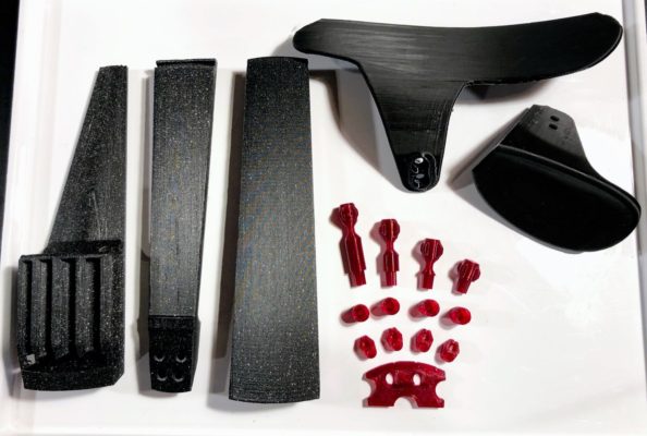
3D Printed Parts
- Neck-Top
- Neck-Base (Oleg or KK depending on pickup choice)
- Body (with or without the hole to install a 1/4″ jack)
- Bridge (Oleg or KK)
- Tuner-Base (x4)
- All four Knobs
- Four Pods, R5 or later
- Chinrest
- Shoulder Rest
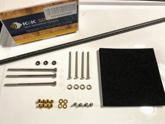
Purchased Parts (Kits are available)
- 3X M4x80 socket head cap screws
- 3X M4 nuts
- 8X M3 heat press inserts
- 4X M3 washers (optional, brass shown)
- 4X M3x8 button head or socket head cap screws
- 4X M3x50 hex head screws
- 4X M3 finishing washers (optional)
- Carbon Fiber rod, 8mm diameter x 350mm length
- Pickup — Oleg’s or K&K Twin Spot
- 4/4 strings, medium tension, for Oleg’s pickup must have steel strings like Helicores or Preludes.
- 1/4″ cable with 90 degree plug
If you are using Oleg’s sensors, you also need:
- 1/4″ jack, additional connectors if desired
- Very small thread forming screws for plastic
Assembly Instructions
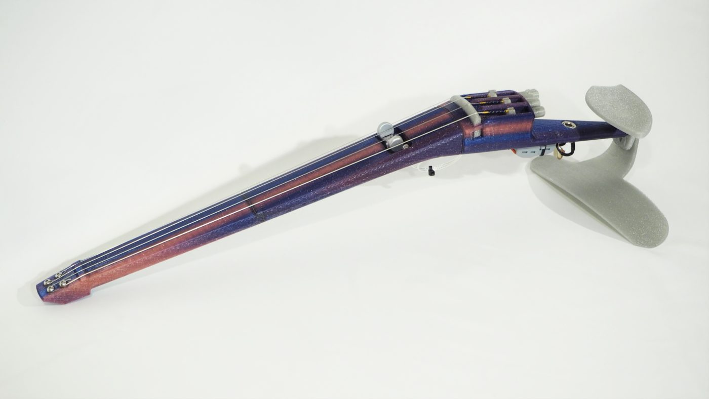
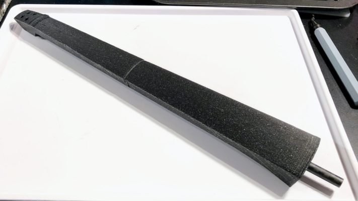
Ready to build your EEV? Here’s how to do it. First, let’s take a look at EEV Arrow anatomy.
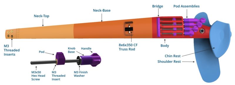
I’ll refer to these parts by name in the assembly instructions.
I highly recommend you purchase a kit. This will make sure you get all the right parts! When designing the EEV, we favored aesthetics and performance over easy to find parts.
For kit options, check the shop.
If you’d like a kit with printed parts, contact me.
If you’d like a kit with printed parts, contact me.
If you’re printing the parts, here are recommended settings.
Neck Parts
For these parts we need to maximize stiffness. There is not much material to work with, so you need dense parts made from a rigid plastic (like PLA) to reduce bending in the neck as much as possible. Carbon fiber PLA would be best, but limits your color options.
- Layer Height: 0.2 to 0.3mm
- Extrusion: 0.5mm nozzle with 0.6mm extrusion width (smaller is ok)
- Perimeters: 5+ with above extrusion settings, 6+ for smaller nozzles
- Infill: 40%-50% (maybe more??) grid, triangular, or other structural fill (not rectilinear!)
- 4-6 floors/ceilings
Body, Chin and Shoulder Rests
These parts also require good stiffness and excellent strength. PLA, PETG, or ABS should work well, although I have only used PLA.
- Layer Height: 0.2 to 0.3mm
- Extrusion: 0.5mm nozzle with 0.6mm extrusion width (smaller is ok)
- Perimeters: 2-3 with above extrusion settings, 3-4 for smaller nozzles
- Infill: 30%-40% grid, triangular, or other structural fill (not rectilinear!)
- 3-4 floors/ceilings
Bridge, Tuner Parts
Pods must be printed SOLID in a high strength material. I use PLA with little to no additives such as carbon fiber, glitter, wood, etc. You must be confident in your settings and material. A defective pod could break in use and cause injury.
- Layer Height: 0.2 or less
- Extrusion: 0.5mm nozzle with 0.6mm extrusion width (smaller is ok)
- Perimeters: 2-3 with above extrusion settings, 3-4 for smaller nozzles
- Infill: 30%-40% grid, triangular, or other structural fill (not rectilinear!)
- 3 floors/ceilings
Make sure that you have all of the parts listed in the parts list, above. You will also need these tools:
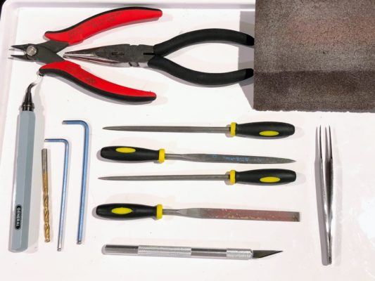
- Calipers or a quality ruler (not shown) (ruler)
- Small files (triangular file is particularly helpful, here’s a decent set)
- 2.5mm and 3mm hex keys (allen wrenches)
- Small torx wrench (depends on your build)
- Deburring tool (much easier and safer than a knife for cleaning part edges, like this one or similar)
- Exacto knife
- Needle-nose pliers
- Snips (scissors will do)
- Electric drill and 4mm bit (not shown, may not be needed)
- Sandpaper (I use a 220 grit foam sanding block like this one)
- Safety glasses (not shown)
- Tweezers
- Soldering Iron (required, not shown)
If you bought printed parts from me, you’ll need to deburr edges and pick off small, mostly loose, bits of plastic. I will have removed most of the support material already. If you printed your own parts, then you know what to do!
Pro tip: use a heat gun to quickly melt away fine strings. Take care, though, because too much heat will anneal sections of the part and cause significant warp.
The neck joint is very fragile. Be careful!
Lightly file or sand smooth all of the contacting flat surfaces on the two neck parts. Test fit often and make small adjustments. The fit should be snug but NOT tight. The parts have thin sections that will easily break if the joint is tight.
IF you do not plan to glue the joint (I would recommend gluing the joint), you may use some mineral oil or cooking oil on the joint to aid assembly.
Whatever you do, make small changes and check fit often.
Be careful to pull straight on parts when separating joints! Do not lever parts!
Run the carbon fiber tube through all three parts. It should fit snug but be very hard to push through. Remove some material from the prints as needed.
If it is very tight or very loose, check the diameter on the carbon fiber rod. Sometimes these are out of spec. It should be 7.90-8.05mm.
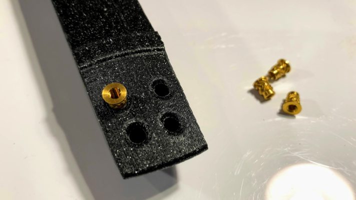
Now that you have confirmed that the parts fit together, go ahead and press the threaded inserts into the neck part. This MatterHackers article has some good information.
It is not difficult!
- Heat your soldering iron to low heat.
- By hand, start the insert in the hole so that it stays. If you need to, remove some plastic with an exacto or a 4mm drill bit so that the insert will sit in the hole.
- Have tweezers handy in case your iron sticks in the insert.
- Insert the tip of your iron into the insert. Press gently until insert is fully seated. Top surface of the insert should be flush with the printed surface. Not quite flush is OK.
- Remove the iron and adjust the position of the insert if needed before it cools.
- Repeat!
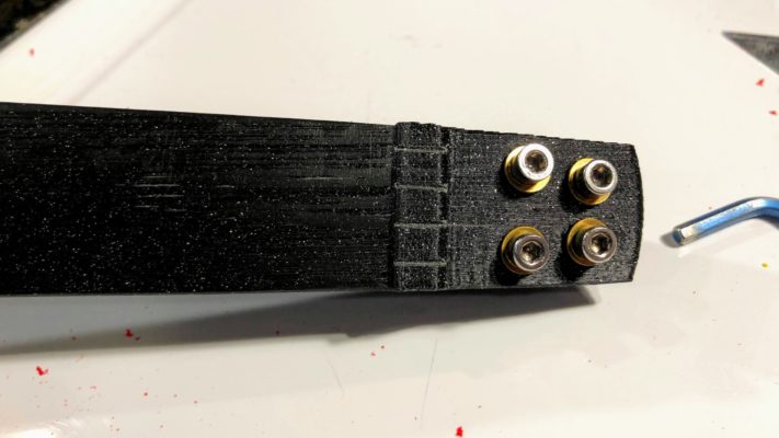
Go ahead and put the the string-fastening bolts on. If you’re using button heads, you don’t need the washers. 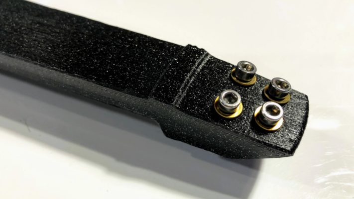
For best performance, use a long-cure epoxy (I use JB Weld Plastic Bonder) to glue the neck joint. Gluing the joint will decrease the bend in the neck, and will provide better and more even string heights to the fingerboard. It’s worth it, even though I hate gluing things.
That said, you don’t have to glue it, and you can always take it apart and glue it later…
Clean the neck joint thoroughly with isopropyl alcohol.
Apply epoxy to all surfaces of the joint. Apply to inside of all truss rod holes. We want the truss rod to also adhere to the parts.
Now slide the joint together and insert the truss rod. Let cure for the full recommended time before sanding and stringing the instrument.
The process for this is the same as pressing inserts in the neck. Drill out the hole, or remove some material with a blade, so that the insert can rest in the hole. Then stick your iron into the insert and guide it into place.
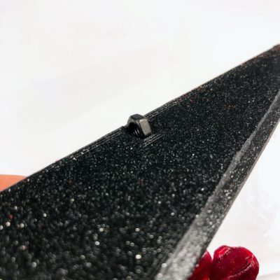
In the image, below, I installed one of the inserts backwards. Find the one that’s backwards, and then don’t install yours that way. But to be fair, it works just fine ‘backwards’.
Now thread these pods onto one of your M3x50 screws one at a time. As you screw it on, some plastic that oozed into the insert will be pushed out by the screw. Use a blade or tweezers to remove this material.
![]()
If you’d like to, go ahead and line all of the pods up on the screw so that they are oriented in the same way. Now you can sand them all at once!
Sand the pods such that all sides are smooth. You shouldn’t need to sand a ton, but a little extra sanding won’t hurt.
The pods should slide with no resistance in their channels. Check this now. If they do not, you may need to sand them a bit more. Lubricate lightly with some mineral oil or another light oil.
Note: It is possible that your body printed poorly and the channels are defective such that the pods will not slide in them. If this is the case, you should consider printing the part again. It is not easy to file, sand, or otherwise work on the inside of the channels.
Give the neck the full time recommended to cure!
The neck is the only part that requires significant sanding. How much you sand is up to you. A smooth fingerboard is nicer to play on than one with noticeable layer lines. I typically spend at least 20 minutes filing and sanding my neck. I have never spent longer than an hour.
While sanding, wear a dust mask to protect from sanding dust. For carbon fiber PLA parts, I wet sand to reduce loose dust.
Sand or otherwise smooth out the layers on the underside of the neck as well. You don’t want any loose strings of plastic to poke you as you move up and down the neck.
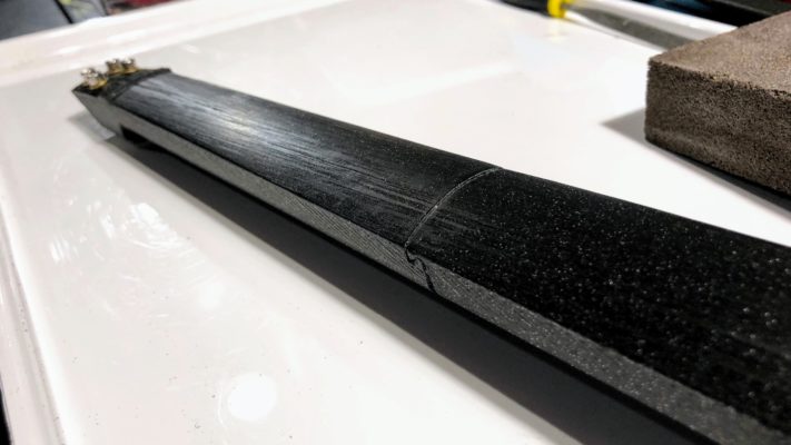
Here’s a neck that I feel is smooth enough. It’s hard to tell by the picture. It’s pretty smooth, but it could be smoother. Some of what looks like texture is the glitter melted in with the plastic. (It’s Proto-Pasta’s black glitter filament.)
It does work to coat the neck with some sort of coating. I have used epoxy. The epoxy coating wears significantly faster than PLA, though, so I am unsatisfied with this as an option and prefer plain sanded PLA. You can buff it up with some mineral oil or cooking oil to restore luster.
For the K&K Twin Spot, stick the discs into the bridge area from the front of the part as shown. Note that this is a K&K Violinissimo, which has a third disc. It did not work well, so that’s why you’re using the Twin Spot.
The cables should run through the provided channels.
Immediately join the body to the neck.
First, press the M4 nut into the tail of the body. You may need to trim the area at the opening with a blade. Then press the nut in with moderate force against a table or counter. It goes in oriented as shown, below.
Now slide the body (the part with the tuner channels) over the truss rod extending out of the neck.
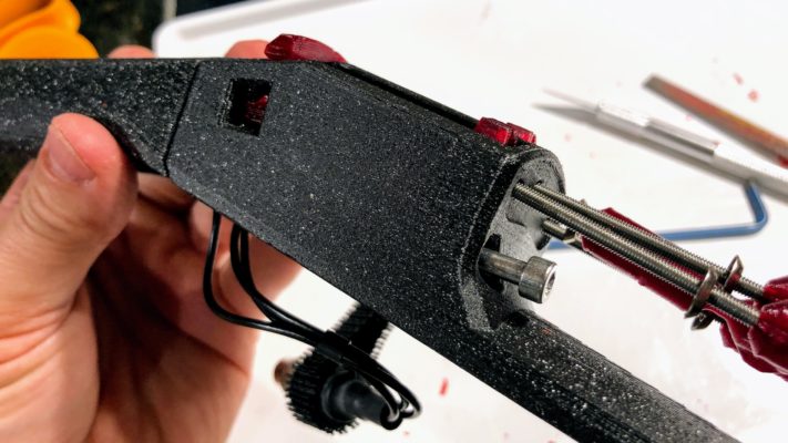
Insert two M4 nuts into their pockets in the neck. My thumb is holding one in in the photo, above. Now hold them in, or flip the assembly over, and install two M4x80 SHCS through the body as shown.
Don’t worry if you haven’t installed your tuners, they just flop around and it’s annoying at this point.
If you are using Oleg’s sensors, you may install them now.
Before installing the sensor, thread the plastic thread forming screw into each screw hole for 3-5 turns. Remove the screw.
Install the sensors one at a time. The sensor with the higher number on the tape tag is more sensitive, and this more sensitive sensor should go on the treble side. The less sensitive sensor goes on the bass side.
<PICS needed!>
To install the sensor is easy:
- Pass the silver wrapped cable through the through hole in the neck.
- Seat the sensor against the neck.
- Install the thread forming screw through the sensor mounting slot.
- Tighten screw until it is just barely snug. You will adjust the sensor’s location later.
- Repeat with other sensor.
I would wait to wire and solder the sensors until you have the instrument strung up. That way if there is some issue you have not already soldered the pickup together.
Let’s get the tuner assembly all ready for strings.
First, check that the M3x50 hex screws fit into your tuner bodies.
[add image of hex screw going into tuner body]If you would like, you may file or sand the tuner body to make it nice and smooth. This is not functional, but can be nice.
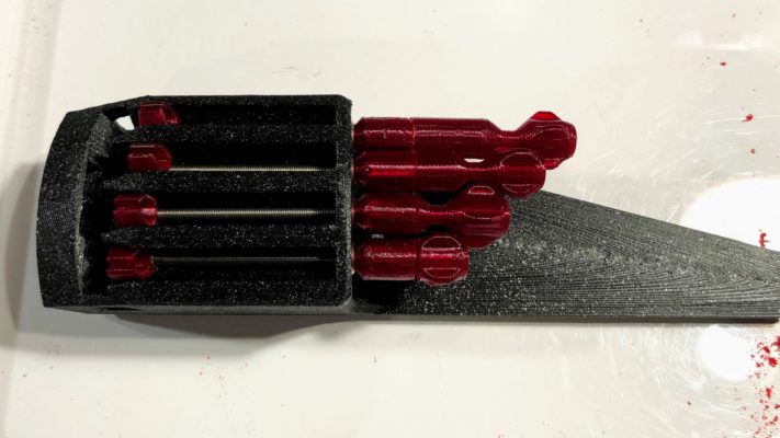
Now let’s install everything.
Here is the process:
- Slide tuner pod into body channel.
- Insert hex screw into knob base.
- If using, place finish washer over screw shaft such that the base nestles into the chamfer of the finish washer.
- Slide screw assembly into hole in body matching the channel containing the pod.
- Thread screw into tuner pod that is placed in channel.
- Repeat for remaining tuners.
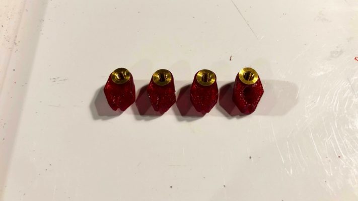
These are the hex screw assemblies:
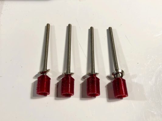
Once they are assembled, you may file and sand the tuner knobs to fit them to the knob bases if desired. Set up at least the shortest one, and you can trade that out between tuner bodies to tune the instrument. Or set up all of them. Try both and see what you prefer.
Here is a completed tuner setup with all of the knobs installed to the bodies.
Let’s get the bridge all set.
First, file the bottom surface as needed so that this face is perpendicular to the back face of the bridge.
[IMAGE NEEDED]If the string grooves seem small, file them in a bit. You can also always adjust these later.
Does it fit into the body? File as needed if it does not. (You may need to file a bit on the body.)
Stick the bridge on there! If you’re using K&K pickups, do your best to make sure the bridge is sitting on the pickups. Look through the little windows on either side to check.
Secure the bridge with a rubber band while you set up the strings, or just remove it and put it back once you are about to install a string.
Take a look at the nut. This is the ridge on the neck that holds your strings up above the fingerboard. The string grooves here should be pretty small, and you will need to make them larger with a small file. I usually file the string grooves a little before I install the strings. Here is my nut, gently filed before I installed strings:
What is important here is that the string touches the nut at its highest point RIGHT before the fingerboard. You don’t want the string to separate from the nut a mm or two back from the start of the fingerboard. If this happens, you could hear some buzzing as the string vibrates against the rest of the channel in the nut.
To ensure good physics here, file away from the fingerboard (to the right in the image) and down (into the screen in the image) a little. This makes sure that the nut channel you make is always sloping up toward the nut. You don’t want it flat, you want it to slope up.
Now it’s time to string this bad boy!
How much travel is needed at the tuners depends on what strings you are using. If you are using synthetic strings, you will need more travel than if you are using steel core strings. Your E string is steel, and may need only 5-10mm of travel.
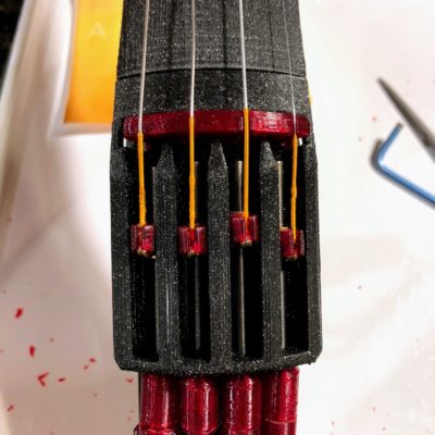
Here is where my tuner pods sit when these synthetic strings are totally slack. I like to line it up so that the thread wrap (orange here) is just barely touching the bridge.
So install the ball end of the strings into the pods (you may need to adjust a pod or two with a blade or file).
Turn the tuners as needed to line them up as shown above, or a bit further back if you are using steel core strings.
Now fasten the strings up at the nut end. They don’t all wrap the same way, so look closely at this image and set yours up to match:
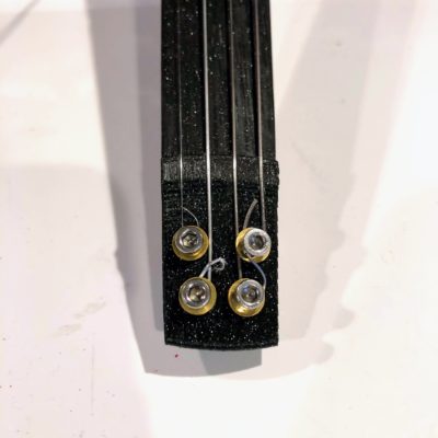
I like to use washers with the SHCS, but if you are using BHCS (with a rounded top) they are a bit wider and the washers are not needed. Really they probably aren’t needed for either…
Tighten down the bolts firmly, but not crazy tight.
Now turn the tuner knobs righty-tighty, lefty-loosey, and bring the instrument up to tension!
(Photos here are from the Modular Fiddle, but the ideas are the same.)
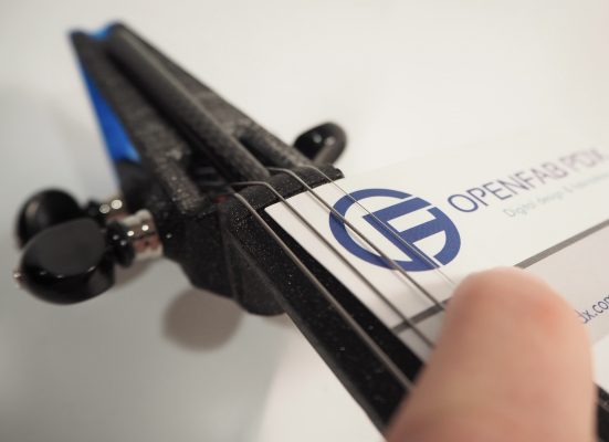
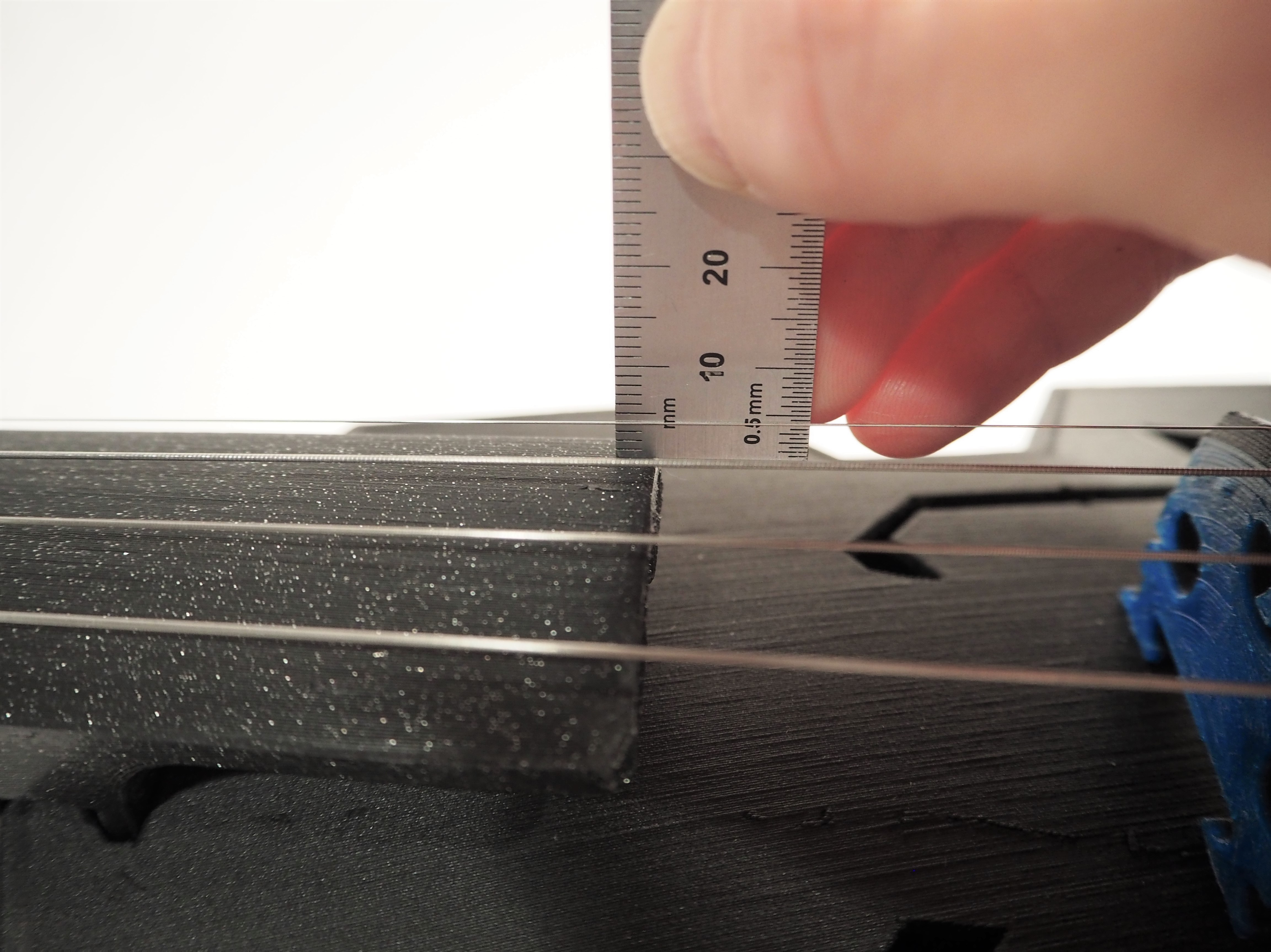
First, check the height of the strings at the nut. You should have about 0.5mm under each string (a little less at the E, and a bit more at the G). One rule of thumb is to allow half the string thickness between string and fingerboard at the nut. Nowadays I can usually feel when I have my strings where I like them, but a business card also makes a good indicator! Mine is 0.4mm thick.
To adjust the nut height, loosen the string that you wish to adjust. Loosen until you can pick it up and move it over and out of the way. With the string out of the way, carefully file the nut grooves deeper. I use a combination of my triangular file to get the depth, and then a round file to get a good profile on the groove and to avoid pinching the strings.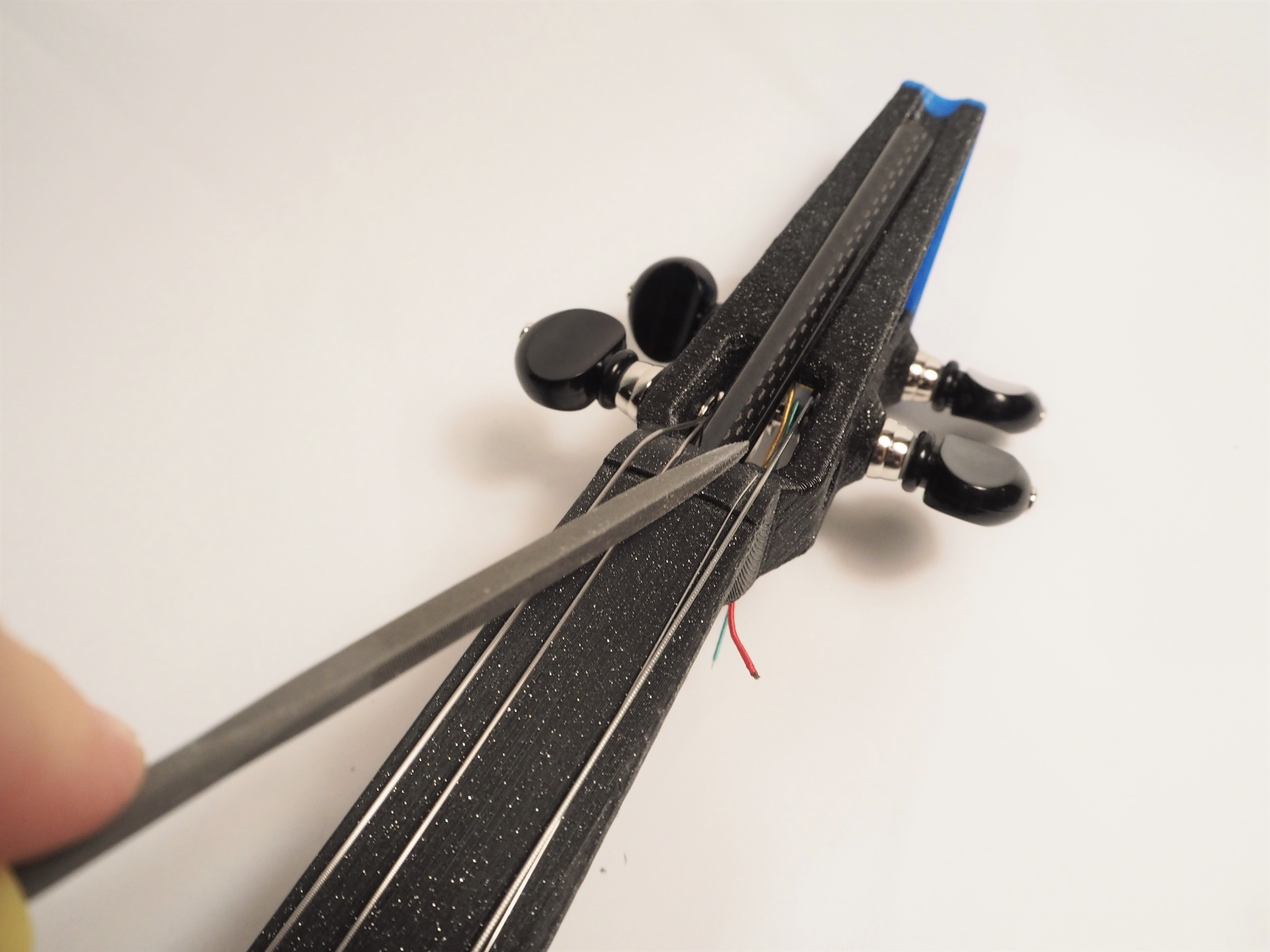
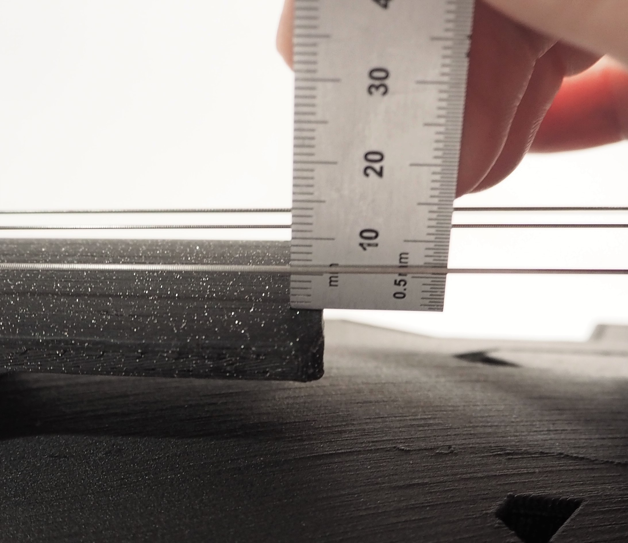
After you’ve adjusted your nut heights, and brought the instrument back close to tune, it’s time to check the string height at the end of the fingerboard. You want them to be about 3.5mm for the E string, 5.5mm for the G, and somewhere in-between for the D and A. These values are approximate! Record your current values. If they are high, you can file down your bridge grooves to lower the string. If you need to drop more than 1mm, you may want to file down the bridge feet a little. It is best to avoid filing deep grooves into the bridge.
For the EEV Arrow, you want to make this measurement about 60mm or 2 inches from the bridge.
If you need to increase your string heights, don’t do anything yet. Give the instrument a few days to settle in and then measure again. In fact, I would say that if your values are within 1mm of nominal, just leave it and measure again in a few days.
Keep track of your string heights (at end of fingerboard) over time — it will give you some good information about how your fiddle is changing over time. All violins change some over time, but these plastic fiddles will change faster. How fast? We don’t know yet!
For K&K Twin Spot
For this one, you can choose to leave the factory wiring in place and secure the 1/4″ jack under the tail of the body. Use zip ties and the factory mount.
[Image needed]You can also cut the factory wiring and wire to a 1/4″ jack installed upright through the tail. You will need to use a cable with a 90 degree plug.
[Image needed]For Oleg’s Magnetic Pickup
For these sensors, you will need to solder the wires together and to the jack. You may also use additional wire to setup the sensors so that you may switch between series and parallel wiring.
To learn more about series and parallel wiring, check out this page.
If you want to try both series and parallel, I would recommend using connectors so that you can change how the sensors are wired. Another option is to use a on-off-on switch, but I found wiring the switch to be a pain.
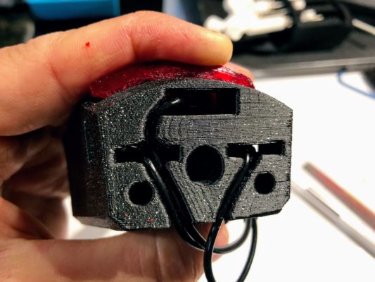
No matter what, first you have to install the plug. Press the plug’s nut into the top recessed hexagon. Twist the plug into place by hand.
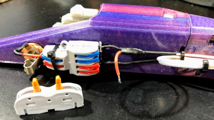
Here is a picture of my current setup, wired in parallel.
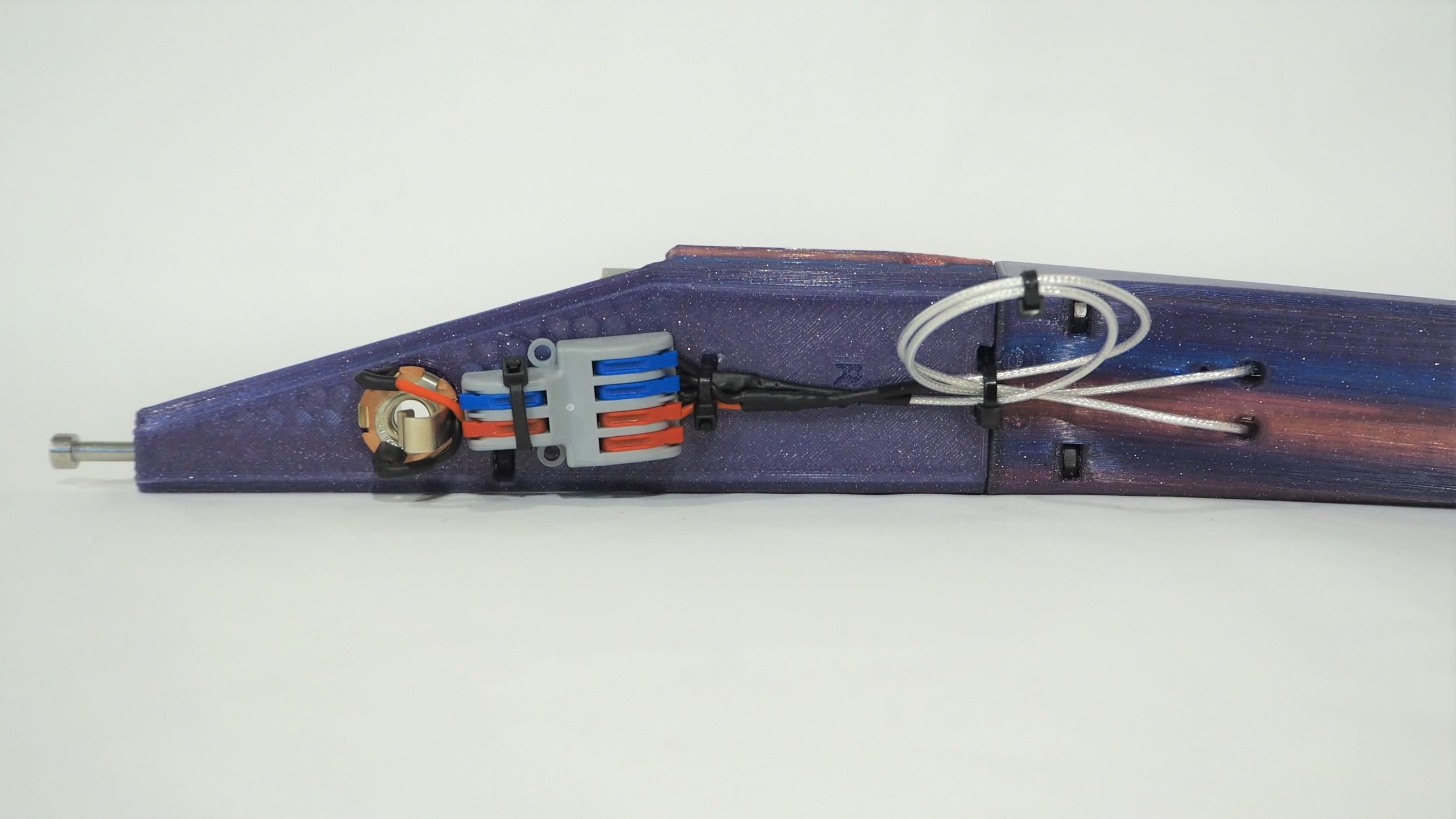
Red is signal and black is ground. The silver sheath on the sensor wire goes to ground, while the interior conductors are signal. Red and black wires are soldered to the jack, and these wires go to the 2 side of a 4-2 connector. On the 4 side, the ground of both sensor go to the blue side, and the signal of both goes to the red.
To change the wiring to be in parallel, I release the signal of one sensor and the ground of the other sensor from the connector.
![]()
Then I use a 1-1 connector to join these wires.
[image]It is worth noting that I should have left more length in these wires!
If you decide that you prefer series or parallel and want to solder the sensor wires direct to the jack, that will improve the sound of the instrument, as more of the signal wire is shielded. You should notice a decrease in background noise.
![]()
![]()
The chin and shoulder rests are easy to install.
Slide the remaining M4x80 BHCS through the shoulder rest, so that the screw head sits in the counterbore.
Then slide the chin rest on.
Now insert the screw into the hole in the tail. Tighten until it starts to come together, and then rotate the chin rest to the desired position. Continue to tighten a bit, and now adjust the shoulder rest as desired.
Tighten the bolt firmly, and check it often, as it will tend to loosen as the plastic compresses.
Once you have everything wired and tuned, play with the position of the magnetic sensors. Once you feel you have a nice balanced sound don’t forget to tighten down the thread forming screw! Not too tight, but nice and snug.
Many of the bolts on this instrument will loosen over time, especially over the first week. Check the tightness of all M4 fasteners (rests bolt and body to neck bolts) often.
If you’re using the 1/4″ jack that sits vertical in the tail, you will need to use a 90 degree connector on your cable. These are readily available.
You’ve done it! Thank you for building an EEV Arrow. Please share photos of your build! You can do that on the Google Group, on the Discord server, email them to me, or just throw them on Instagram with the tag #EEVArrow and #FFFiddle.