
The Modular Fiddle is an open source and upgradeable 3D printed string instrument.
Here you’ll find all the documentation you need to build your own Modular Fiddle, including step-by-step instructions.
This page has the most up-to-date Modular Fiddle build instructions, parts lists, and project info. If you aren’t sure you have the latest files or information, double check this page.
Print files are freely available for the 4-string violin Modular Fiddle. To access files for other variations you have three options.
- Become a Patron (you get full access and other perks, including a store discount)
- Purchase the files (one-time download)
- Purchase a kit (configure it for your desired variation and I’ll send you the matching 3D files via email)
Building a fiddle? There is a Discord Server full of conversation and problem-solving. You can also check out the now inactive Google Group.
The Modular Fiddle has four primary variations.
4-String (violin and viola), 5-String (short, medium, and long), Hardanger Fiddle, and Treble Viola da Gamba
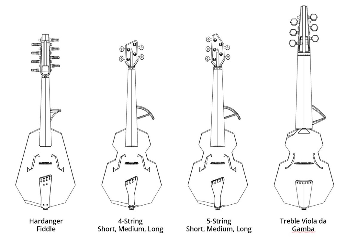
Within each variation there are options.
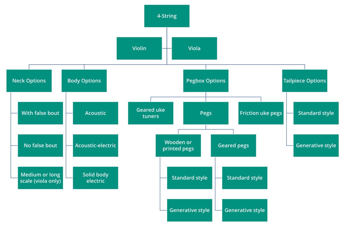
Let’s look at options for the 4-string.
The Basics
The 4-string violin is the basic design, and all playing dimensions are standard 4/4 violin. The 4-string violin can also convert to a 3/4 scale violin, just use the 3/4 neck and bridge! All design and 3D print files for the 4-string violin are freely available via the link below.
(Update 4/28/2023 — I continue to have occasional server issues. If the above file does not download, you may access the same zipped folder via Google Drive here.)
If you want to print a 5-string, or some other instrument, first check to make sure the neck and body of the 4-string fit on your printer. If they fit — you can print any version of the Modular Fiddle.
As shown, above, there are a lot of options to choose from. Without a complicated table, or intimate knowledge of the design, it can be difficult to know what parts to print.
To make this process easier, 3D print files are included with the purchase of an off-the-shelf parts kit. Your 3D print file package will include only the parts you need that match your selected options.
4-String Viola, 5-String, Hardanger Fiddle, and Viola da Gamba 3D print files are available for purchase if buying a kit is not a great option for you (for example if you live outside the US and shipping is expensive).
If you are confused, or can’t figure out how to get what you need to build the fiddle of your dreams, please get in touch through the contact form or give me (David) a call, 503-967-5542.
Licensing
This design is licensed CC-BY. You may remix and distribute (or not) to your heart’s content. Credit OpenFab PDX and link to this page when possible. You may use this design for commercial use. I know this may be confusing, because the designs are offered for sale here. I would like you to purchase my kits and support my work, but in the end I also want more cool 3D printed violins out in the world. So please remix, sell your Modular Fiddle builds — whatever you want to do! But do please tell me about it so I can be excited.
Frequently Asked Questions
All basic 4-string print and design files are available here.
If you’re building a viola or a 5-string, those files are not included in the above package. If you purchase a kit for your build, I’ll send you the right print files via email. If you need to check to see if the parts fit on your printer, use the link above to download the basic design package. The body and neck on the 4-string are as large as any other design, so if you can fit those parts, you can fit any other.
Some print files are for sale in the shop (like the hardanger and viola da gamba).
Patreon Patrons have access to all files, including early releases.
If you can’t find what you need, get in touch on discord or via the contact page.
When printed well with the right materials and set up correctly, the Modular Fiddle is a joy to play and gives the sound of a good wooden violin with a mute. It does not project nearly as well as a wooden instrument and is always quieter. It is reduced in timbre, but offers enough resonance and timbre to satisfy most musicians for practice and informal performance settings.
With a pickup, the Modular Fiddle can make a good performance instrument. However, the instrument MUST BE properly set up. Poor string heights, incorrect bridge placement, or bad print settings will ruin your instrument.
3/4 scale parts are available for the 4-string violin, but not for any other variation.
No other scale parts are currently available.
If you are interested in a scale instrument, please let me know through the contact page.
Whatever you are building, I would recommend purchasing an off-the-shelf parts kit. The kit listing clearly shows you the tuner options and provides additional information.
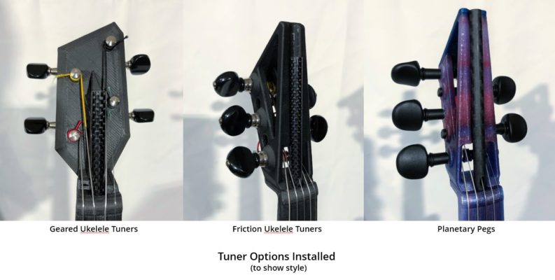
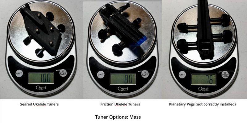
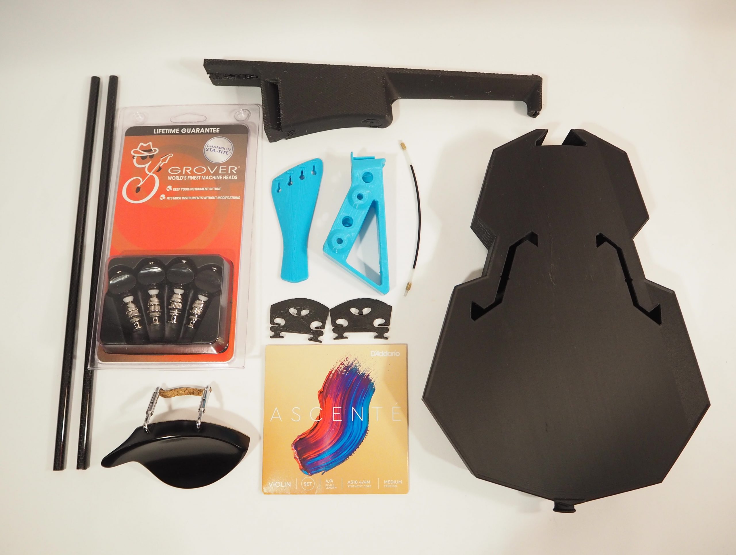
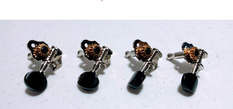
Generally, I recommend the Grover 9NB geared ukelele tuners shown at left in the images, above. These give fine-tuning control but add about 35 grams of weight when compared to planetary geared pegs. They also offer a unique style of pegbox. For these, use the Pegbox-GuitarStyle-Grover9NB pegbox.
Planetary geared pegs offer the best performance and weight, but are the trickiest to install and require luthier tools. For this option, print Pegbox-Pegs and ream to fit with a violin pegbox reaming tool. If you choose to try this option, print a couple extra pegboxes for practice! You’ll need them.
You could use the friction ukelele tuners, these are the Grover 6 series. I no longer recommend them, though, as they are difficult to keep in tune. For these, print a pegbox with Grover6 in the name.
Want to go full 3D printed? You can print your own pegs. (Not shown above,) They hold tension well but must be properly lubricated to be usable (I use plain bar soap and chalk). You may need specialized luthier tools to set them up.
Yes, but they won’t work very well.
For the four and five string instruments there is a Pegbox-Pegs file that you can use for standard violin friction pegs. You will need to use a luthier’s pegbox reamer to size the peg holes. You may also need a peg shaving tool to properly size the pegs. If you are using pegs, I recommend using a tailpiece with fine tuners.
You can also use the Pegbox-Pegs file with Wittner fine-tune pegs, or another brand of geared peg (check sizing before you order). You will need to very carefully install these pegs for proper function, there is not a lot of room for error. If you choose to try these pegs, print a couple extra pegboxes for practice!
Yes! There are a variety of options for how to make an electric Modular Fiddle. Check this blog post for the latest info.
This is not yet known, but my experience shows that a well-printed Modular Fiddle shows no degradation after two years and should play well for at least 3 years. If you purchase a kit or a complete build from me, I offer replacement printed parts at a reasonable cost. So if your instrument does start to degrade, new parts (and possibly upgraded parts) are not out of reach.
Most Modular Fiddles are built using PLA plastic. PLA will fail rapidly at elevated temperatures, so take care to keep your Modular Fiddle below 90F. At these elevated temperatures, the parts will begin to slowly warp with string tension. If your fiddle hits 120F, it will warp beyond repair in minutes.
No! Like a wooden violin, high temperatures will destroy your Modular Fiddle.
If you build your fiddle with annealed high temperature PLA, though, you can do whatever you want with your fiddle. Leave it in the sun, in the car — whatever!
Annealed part kits are available! Build yourself a bomb proof fiddle.
Most Modular Fiddles are built using PLA plastic. Unlike a wooden violin, where failure will take longer exposure to high temps, PLA will fail rapidly at elevated temperatures, so take care to keep your Modular Fiddle below 90F. At warmer temperatures the parts will begin to slowly warp with string tension. If your PLA fiddle hits 120F, it will warp beyond repair in minutes.
What we don’t yet know is if you can play your instrument in the sun on a warm day. It is possible that if the instrument is moving around in the air, that would provide enough cooling to prevent it from hitting that critical 120F temp. Until this is tested, please avoid playing out in the sun on a warm day.
Like all violins, the Modular Fiddle has a settling period of a week or two. During this time the instrument will go flat between playing sessions. Also during this first couple weeks, it is crucial that you check the tension in your tuner screws. As the plastic settles, the ukelele tuners will become looser, and will not hold tension properly. Also, note that Modular Fiddle may not work for high tension strings! Use medium tension.
While tuners are the most likely suspect, this instrument is designed to live at the boundary between failure by plastic creep and violin performance. It’s possible that your parts are not stiff enough, either due to print material or print settings.
If your tuners are tight, your instrument has settled, and you continue to lose tension…
- Double check that your tuners are tight.
- Some tuners have more ‘play’ in them than others. Try tuning your instrument by aiming high, and then descending down to pitch. Aim high enough that when tuned the tuning peg is past the bit of looser travel.
If you’re still having trouble, take some notes:
- How much pitch do you lose and how quickly? On all strings?
If you are losing pitch on all strings and you are confident that your tuners are not slipping, then it is possible that the neck or body is warping.
- Measure the curvature in the fingerboard every few days, is the neck bending?
- Is there visible deflection in the top plate of the instrument?
If either of the above is true, you may need to print your parts again with a stiffer material or with more dense print settings.
What You Need to Build a Modular Fiddle
Use the tabs below to view the parts list for each variation. I will no longer link to Amazon products and am no longer a participating Amazon Affiliate. Please purchase a kit from me or find the parts from your local music store.
3D Printed Parts (link to kit)
I recommend Proto-Pasta materials, especially their carbon fiber PLA (affiliate link) for the bridge and body. Use this affiliate link to buy their filament and support my work as well.
- Neck-4String
- Pegbox-4String
- Body
- Bridge-4String
- Tailpiece-4String
- Saddle and end pin (for some bodies)
- Chin rest (may use off-the-shelf)
Purchased Parts (link to kit)
- Grover 9NB geared ukelele tuners (recommended)
- OR Perfection planetary geared pegs 7.8mm
- OR Graph-Tech Tune-a-lele Tuners (tend to break)
- OR Ukelele friction tuners, Grover 6B set of 4
- OR Wittner planetary geared pegs 7.8mm
- 4/4 strings, medium tension, D’Addario Ascente or similar
- (for viola get medium tension strings for medium scale)
- Tailgut (Wittner nylon or similar)
- 2X M3 heat press inserts and 2X M3x45 flat head screws (for printed chin rest)
- Two 6x8x330mm carbon fiber tubes from Arris or elsewhere
- For V3 builds: 4X M3 heat press inserts, 4X M3x10 socket head cap screws
3D Printed Parts (link to kit)
(files available for purchase here)
I recommend Proto-Pasta materials, especially their carbon fiber PLA for the bridge and body. Use this affiliate link to buy their filament and support my work as well.
- Neck-5String
- NeckJoint (for medium and long only)
- Pegbox-5String
- Body
- Bridge-5String
- Tailpiece-5String
- Saddle and end pin
- Chin rest (or use off-the-shelf Guarneri style)
Purchased Parts (link to kit)
- Five geared Grover 9nb ukelele tuners (purchase two sets of 4 or a kit from me)
- OR five Perfection planetary geared pegs 7.8mm
- OR Five GraphTech Tune-a-lele tuners (not recommended, tend to break)
- OR five Ukelele friction tuners, (purchase two sets of 4 or a kit from me)
- OR five geared planetary pegs, Wittner 7.8mm
- Helicore 5-string string set medium tension (violin length for short size)
- Two 6x8x330mm carbon fiber tubes from Arris or elsewhere
- 2X M3 heat press inserts and 2X M3x45 flat head screws (for printed chin rest)
- For V3 builds: 4X M3 heat press inserts, 4X M3x10 socket head cap screws
Medium and Long Also Require
- 4X M3 heat press inserts
- 4X M3x12 socket head cap screws
- Long strings: Helicore viola long scale light tension string set plus Helicore viola long scale light tension E
- Medium strings: Helicore viola medium scale medium tension string set plus Helicore viola long scale medium tension E
3D Printed Parts
(files are available for purchase here)
Contact us if you are interested in a kit and I can put one together for you.
I recommend Proto-Pasta materials, especially their carbon fiber PLA for the bridge and body. Use this affiliate link to buy their filament and support my work as well.
- Neck-Hardingfele
- Pegbox-Hardingfele
- Body for Understrings
- Bridge-Hardingfele
- Tailpiece-4String
- Saddle and end pin
Purchased Parts
Currently kits are not available for Hardanger builds. Contact us if you are interested in a kit, though, and I’ll put one together for you.
Now available with Tune-a-lele tuners!! This is a great setup for the Hardanger.
- 8 GraphTech Tune-a-lele tuners (two sets of four)
- OR Ukelele friction tuners, two sets of Grover 6B set of 4
- OR 8X geared planetary pegs, Wittner or Perfection 7.8mm
- OR wooden/printed pegs
- Hardingfele strings, 11 weight, HFAA
- Understrings, steel ball or loop end guitar strings are best, as standard understrings may be too short. Size PL009 (0.228mm) for upper strings and PL010 (0.25mm) for lower strings.
- Steel wire, ~1.5mm diameter, stainless or galvanized
- 4/4 Guarneri style chin rest
- Two 6x8x330mm carbon fiber tubes from Arris or elsewhere
Gamba builds require specialized luthier tools. Consider purchasing a built Gamba.
3D Printed Parts
(files are available for purchase here)
Currently kits are not available for Gamba builds. Contact us if you are interested in a kit.
I recommend Proto-Pasta materials, especially their carbon fiber PLA for the bridge and body. Use this affiliate link to buy their filament and support my work as well.
- Neck-TV
- Pegbox-TV
- Body-TV
- Bridge-TV
- Tailpiece-TV
- Saddle-TV
Purchased Parts
Contact us if you are interested in a kit and I’ll put one together for you.
The Gamba as designed can only be built with pegs. Wittner geared pegs or wooden pegs will work but require a pegbox reaming tool and peg shaver (for wood pegs).
Building a Gamba is not covered in the build instructions.
- 6X geared planetary pegs, Wittner Viola pegs 8.6mm
- OR wooden/printed pegs
- Treble Viol string set — Aquila Red recommended
- Fret Gut, Aquila synthetic 0.8mm gauge recommended
- One 6x8x330mm carbon fiber tube from Arris or elsewhere
- One 8x10x400mm carbon fiber tube
- Pickup, if desired, Realist Copperhead for Violin or Viola
Assembly Instructions
Here you’ll find the full assembly instructions for the 4-string (violin or viola), 5-string (all lengths), and Hardanger Fiddle. Details for the Viola da Gamba are not included. Select the drop-down on each step for images and details.
The Modular Fiddle has versions, revisions, and variations. It’s a lot to keep track of!
Versions are V1, V2, and V3. There is no reason to build a V1 Modular Fiddle, it is inferior.
V2 is improved in the body and neck and offers improved acoustics and a better build experience. V2 will no longer be actively developed. If you would like to avoid having to use heat-press inserts, though, V2 is a good option.
V3 has all the V2 improvements and uses heat-press inserts and bolts to fasten the neck and body, resulting in an easier build (much less filing and sanding) and a more durable instrument. In addition, V3 has improvements to the end-pin and saddle which improve strength and performance for higher tension instruments (5-string, hardanger, Gamba, etc).
V4 has all the greatness of V3 but an improved pegbox and neck connection. This is easier to assemble, gives greater ease of exchanging parts down the road, and significantly reduces stress on the printed parts.
Pro tip: V3 and V4 bodies are interchangeable.
For V4 and later, all parts much match in version number.
Revisions are shown in the part name after the version number, or after the part name if there is no version number. For example, Body-V3-R3, where V3 is the version and R3 is the revision. Generally speaking, you want to use the latest (highest) revision of a part, but this is not always the case. Review the notes included with the files (the readme) to determine what revision is right for you.
Variations are instruments that are not 4-string violins. This includes electric bodies, the hardanger fiddle, 5-string violin, and violas. There are a lot of variations. To access CAD for variations you must either purchase the files, purchase a parts kit, or become a Patron. If you can’t find what you want, please get in touch!
You can leave the printing to me and buy a kit here.
If you’re printing the parts, read through this blog post for recommended settings and possible problems.
I recommend Proto-Pasta materials, especially their carbon fiber PLA for the bridge and body. Use this affiliate link to buy their filament and support my work as well.
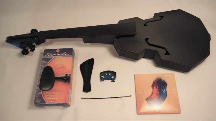
Make sure that you have all of the parts listed in the parts list, above, or purchase a kit.
For V3 and V4 builds, 3D printed chin rests, medium and long instruments, and viola da gamba, you will need to use a soldering iron for the heat-press inserts.
You will also need these tools, listed counter-clockwise from top left in image:
Basic Tools
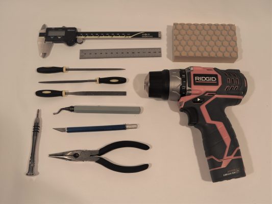
- Calipers or a quality ruler
- Small files (triangular file is particularly helpful)
- Large file (not shown)
- Small philips screwdriver that fits the tuners
- Deburring tool (much easier and safer than a knife for cleaning part edges)
- Exacto knife
- Needle-nose pliers
- Electric drill (may not be needed)
- Sandpaper (you can get by with two stages, 100 and 220, but now I use three or four up to about 400 grit)
- Safety glasses (not shown)
If you are installing planetary geared pegs (Wittner or Perfection) you will need a pegbox reaming tool with a 30:1 ratio. If you are planning to install wooden or printed pegs, you may also need a peg shaving tool.
Bonus Tools
Now that I am making more fiddles, I have refined my tool selection. These are the ‘extra’ tools I use now to perfect my builds. The little files are really great for dialing in action at the nut.
- Nut files (0.4mm width for E, 0.8mm width for other strings)
- Very thin round file (mouse tail file)
- Sandpaper mounted on a wall sanding block
- Curved fingerboard scraper
If you bought a kit from me I have done some work for you already. You might need to deburr some edges (cut sharp edges down to make them not sharp) and remove some bits of loose plastic. If you printed your own parts, then you know what to do!
Protect your hands! Edges of 3D prints can be VERY sharp and can cut you. I wear cut-resistant gloves when doing finishing work.
Pro tip: use a heat gun to quickly melt away fine strings. Take care, though, because too much heat will soften sections of the part and cause significant warp.
If you bought a kit from me, I have already adjusted the joint fit to be about right. You may adjust as desired. Read through this step regardless, though, to learn about how to pull apart the joints safely.
 For V2 builds there are two dovetail joints; one between the pegbox and neck and one between the neck and body. Filing and sanding the parts so that the joints fit is one of the first things you should do. That’s because this is when you are most likely to break something! Use care when testing the joints.
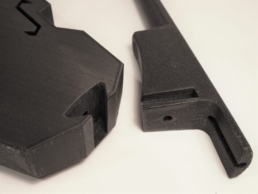
Be careful to pull straight on parts when separating joints! Do not lever parts! The joints are not designed to bear much load. A gentle whack with a rubber mallet, or on a tabletop, to loosen the neck from the body is OK.
For both the pegbox joint and the body joint, the tuning process is the same. Gently file the positive and negative parts of the joint to remove blobs of plastic and to smooth out the joint surfaces. Test the joint often as you adjust — file and sand just enough for good performance!
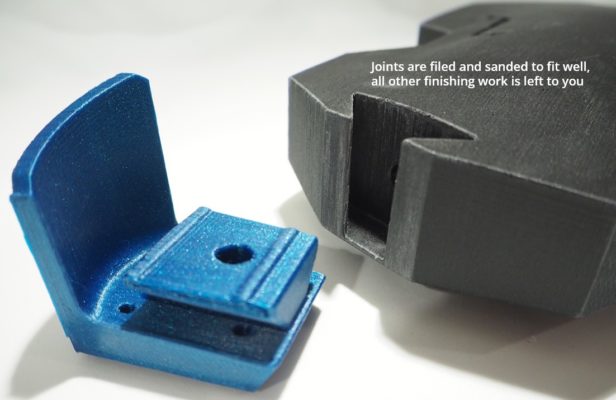
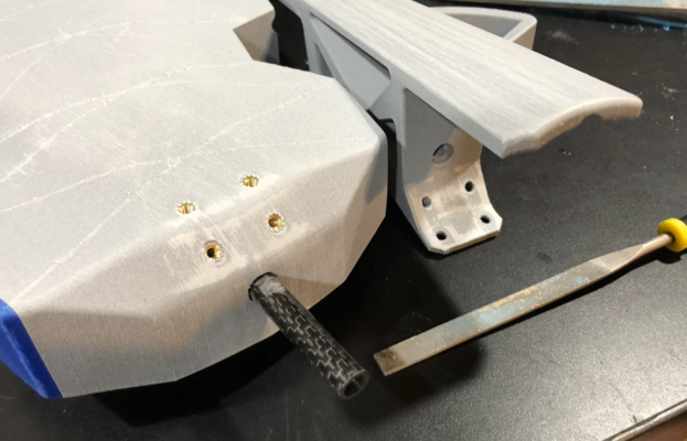
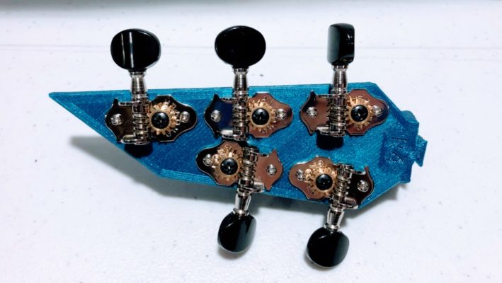
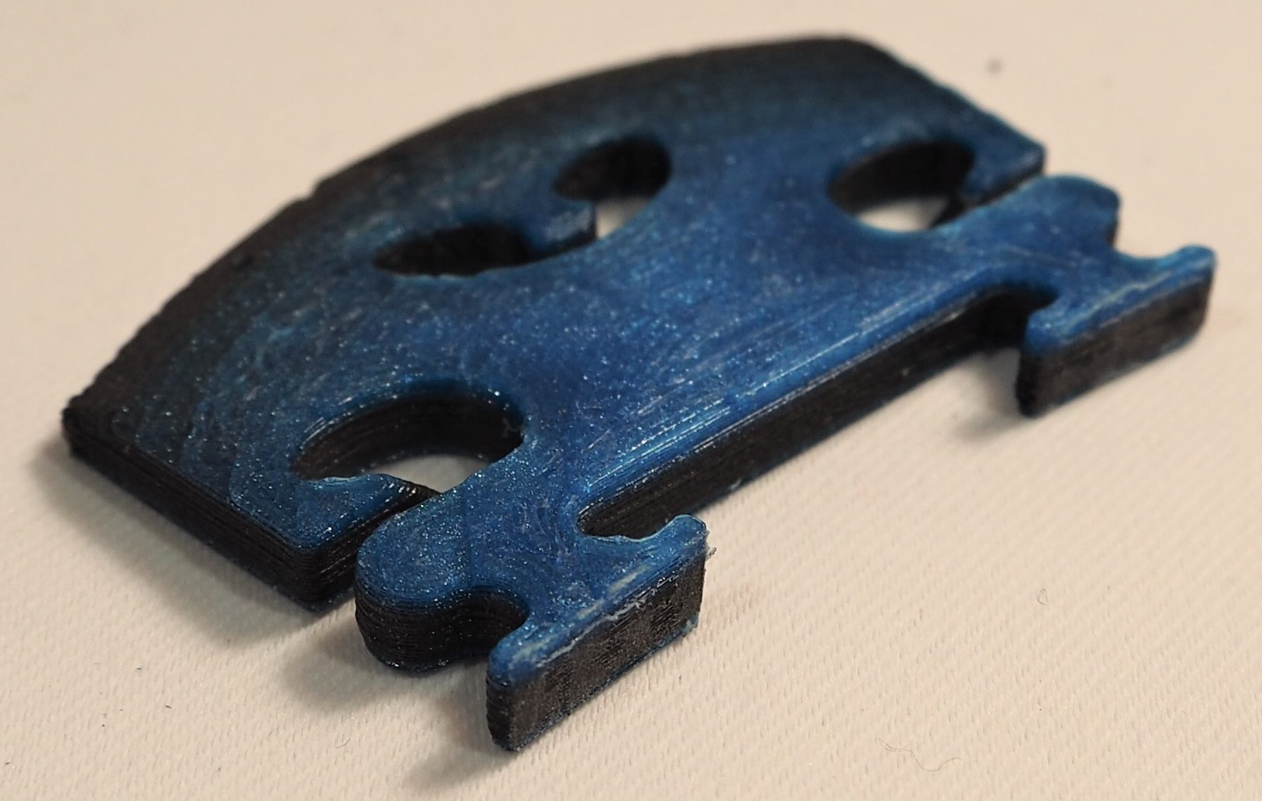
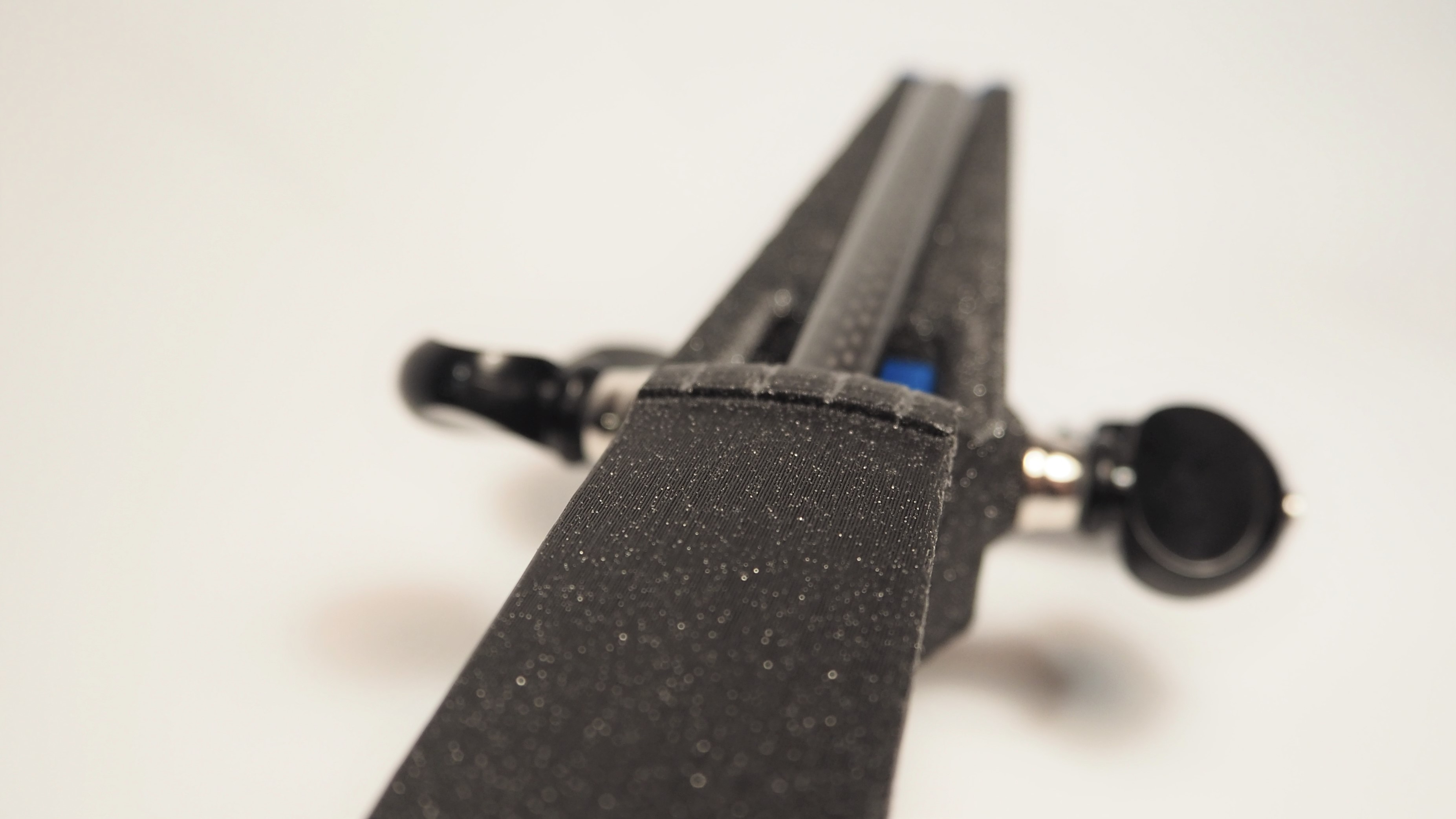
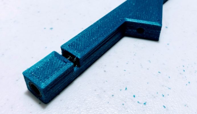
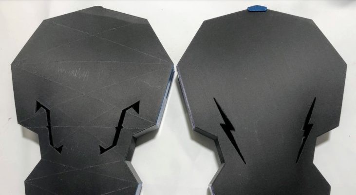
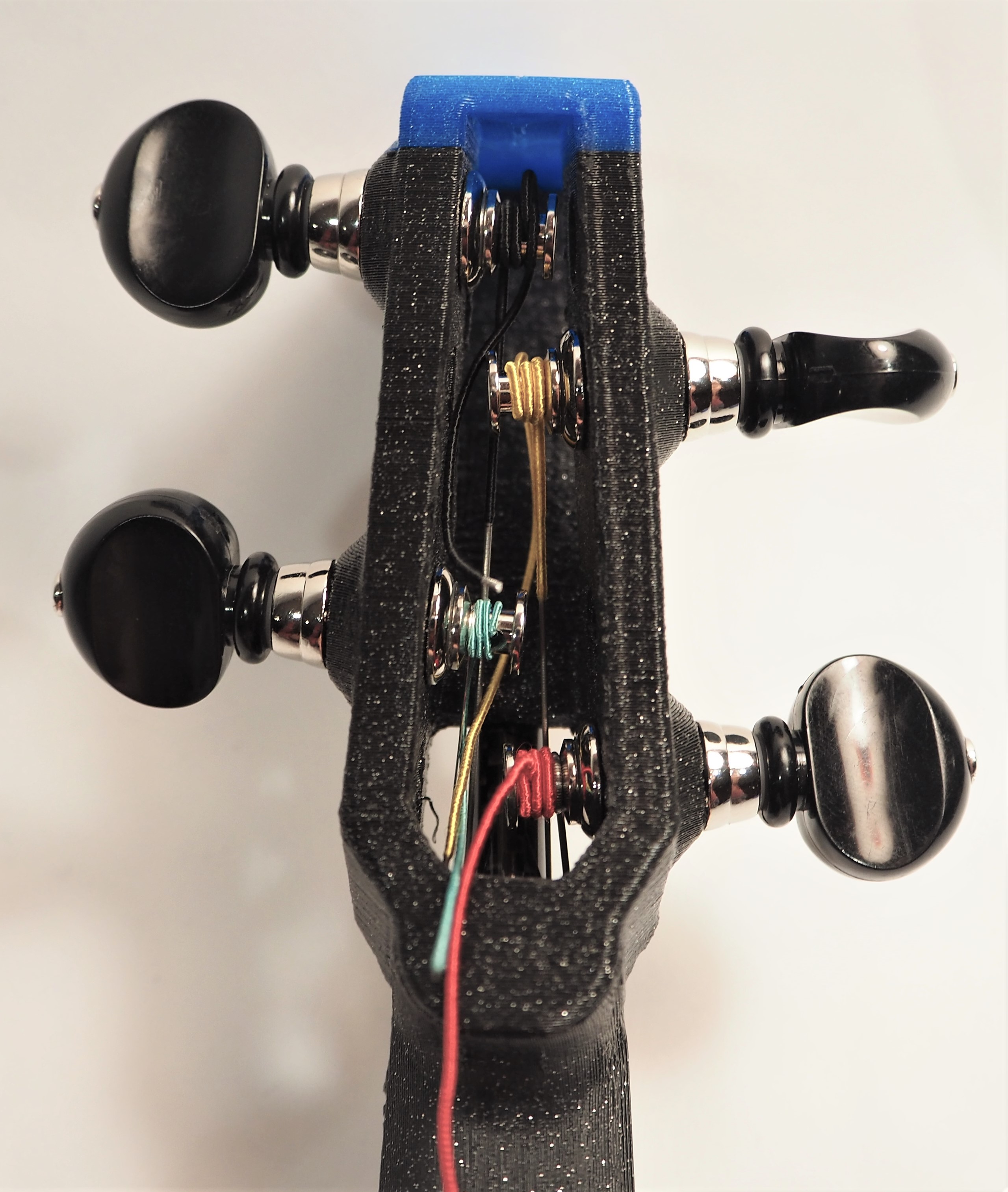
On most neck joints, you will see two bars of material. Sand or file these bars down very gently until the neck fits exactly. The neck joint of this five string (blue part) shows the two bars that need to be adjusted.
Once you think the fit is about right, rub a rag or paper towel with a bit of cooking oil over the joint surfaces. This little bit of lubrication will make a big difference.
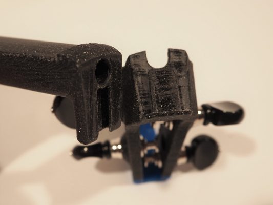
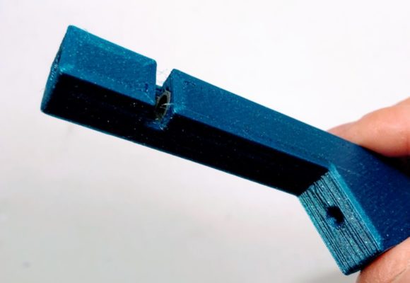
The pegbox joint is typically fairly loose, and those parts should pull apart easily. The truss rod will support the load for this joint. In the photo, here, you can see that both the pegbox and neck have been filed and sanded. (Please ignore the fact that my pegs are installed. Yours should not be.)
The neck to body joint is typically tight, but should not need to be forced together. If you force it, the body may crack. The neck should press into the body with moderate finger pressure, like about as much as you can squeeze between one finger and thumb. When I’m separating the neck and body, though, mine often require a tap on the table to get started.
You can see my neck-tapping removal technique in this youtube video:
Versions 3 and 4 use heat-press inserts and bolts to attach the neck and body. This is much easier, and gives you a stronger and more durable connection!
Note: V3 and V4 bodies are interchangeable.
Some V3/V4 bodies have a different saddle design and require that you print the end pin separately and bond it to the body. I recommend using this design for long-term durability.
Body Assembly Overview
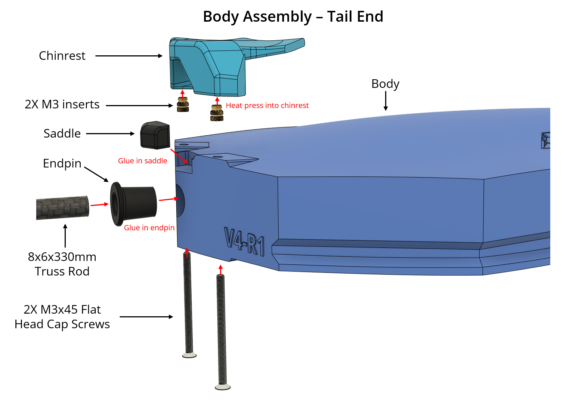
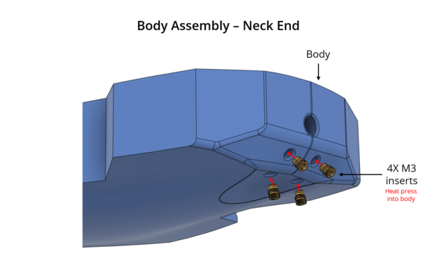
Let’s go through the steps required to set up a V3/V4 body with the updated saddle and end pin.
Installing Saddle and End Pin
First let’s set up the saddle and end pin. Then we’ll install the heat-press inserts. That way if something goes wrong you haven’t wasted your inserts.
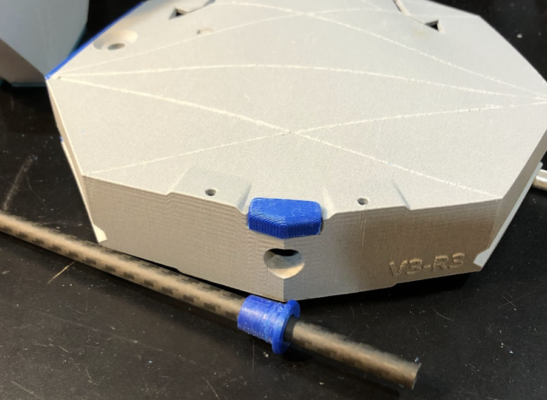
Here is a V3-R3 body with the saddle and end pin fresh off the 3D printer. You’ll want to print the end pin completely solid and the saddle nearly solid.

Lightly file the saddle area on the body to clean up any loose bits. Does the saddle fit? If not, file the saddle (not the body) as needed to fit into the body. It goes in like this:
Set the saddle aside and let’s fit the end pin. This one is a bit more labor intensive. It needs to fit close to the truss rod, and also needs to go far enough into the body.
First, let’s fit the end pin to the truss rod. It prints undersized, so you’ll need to drill it out. Use a 5/16 drill bit, and drill as needed to get a good close fit that allows you to pass the entire truss rod through the end pin. It might take a fair amount of drilling and from slightly off angles to open it up a bit.
Take a moment to see if the truss rod fits into the other body hole (up by the neck). If it is loose, that’s not ideal but it is OK. If it is too tight, DON’T FORCE IT. Drill the body out as needed with a 5/16″ bit. If you force it you will crack the body.
Pro Tip: Before you finish drilling out the endpin, leave it stuck on the drill bit and use the drill like a lathe while you use a file to smooth and file down the outer surface.
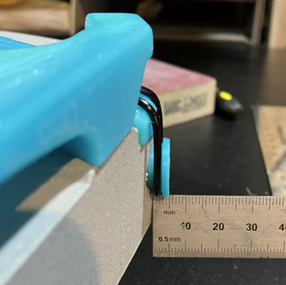
Now file the exterior of the end pin (the round part that goes into the body) until it fits correctly in the body. You want it to fit tight with enough room to hold the tailgut. It usually sticks out about 5mm from the outermost edge of the body, see below.
Before we glue let’s check fit one last time. Insert the truss into the endpin, then insert the truss and end pin into the body. Seat everything. Does the truss slide with some resistance through the body? Is the endpin seated far enough in, but not too far? If so, you’re ready to glue.
I am using this amazing adhesive called 3D Gloop. It is a life-changing solvent adhesive that makes fast and EXTREMELY PERMANENT bonds between PLA parts. So that’s what I use to glue the endpin. You could also use epoxy, Gorilla Glue original formula, or your favorite rigid adhesive.
The saddle does not necessarily need to be glued, and there are times when I wish I could take it out and put in one of a different height. So it’s up to you whether or not you glue the saddle. If left unglued, it may fall out easily, so watch out for that. I glue the saddles on my customer builds.
Glue the parts in following the adhesive manufacturer’s instructions. Clamp and let sit as needed.
Installing Heat-Press Inserts
If you want more detailed instructions for installing heat press inserts, do an internet or YouTube search for “install heat press inserts.”
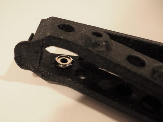
Inserts are installed into the four holes on the back side of the body near the top. You don’t need to prepare the holes, just heat up your soldering iron and stick the inserts in! Make sure they go all the way in and that they are installed perpendicular to the print surface. You want the plastic to make contact between the neck and body, not the metal inserts. If you aren’t sure, go an extra mm.
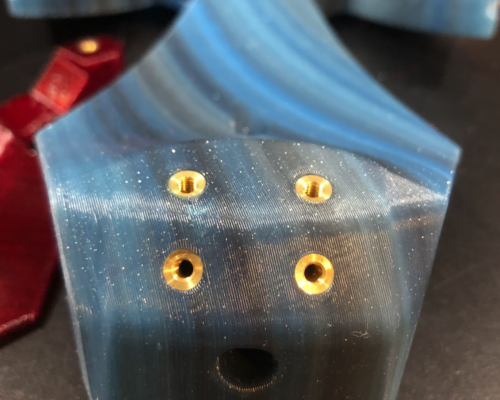
Here are inserts installed on a V3 solid body.
Below is a photo of a V3 acoustic body and neck ready to install. Note that the insert area has been filed and sanded after the inserts were installed to make sure the parts mate clean and flush.
V4 has an improved neck/pegbox joint that is very easy to fit.
First, make sure you have a good fit to the neck/pegbox truss rod. It should slide into both parts with some resistance, but you should be able to pull it out without a vice or pliers.
If the truss wiggles perpendicular to the hole or falls out easily, it is too loose. This could result in too much bending in the neck or unstable tuning.
If it is too loose, you have a few options.
- Use a 3D print pen to add material (great if you have a 3D print pen)
- Glue the truss in (best not to)
- Place a plastic ziplock bag around the truss to add thickness (suggested by another builder, I though this was a great idea!)
- Think of another way to add material (I’m sure you can come up with something…)
If the truss is too tight in either the pegbox or the neck, you have a few options:
- Lubricate the truss (a bit of mineral oil or silicone lubricant can do wonders)
- Drill out the parts (I have a set of fractional bits from 7.9-8.1mm for this purpose)
- Heat the parts (VERY CAREFULLY) and insert the truss to widen (this is risky, and the part could contract when cooling and make it even tighter)
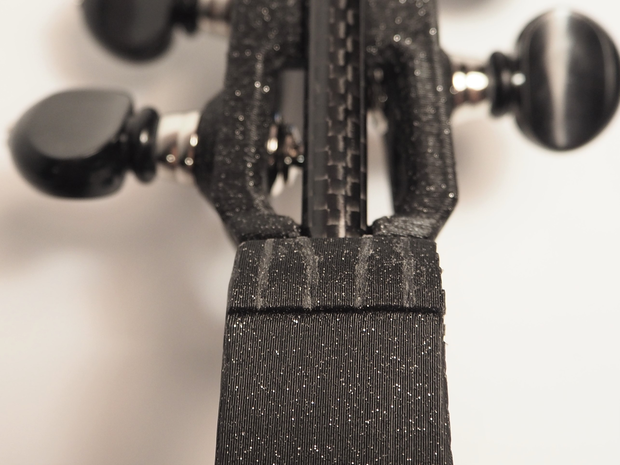
Once the truss fits well, now you can adjust the locating nub (best to file the nub on the pegbox) to fit securely with the neck. The two parts should fit together snugly with a minimum of up/down or side-to-side play in the joint.
In the image, below, I used a 3D print pen to add material to the neck to get a snug fit around the pegbox nub.
This pegbox, below, needed very little adjustment at the nub. Note: you probably haven’t installed tuners yet and that’s good.
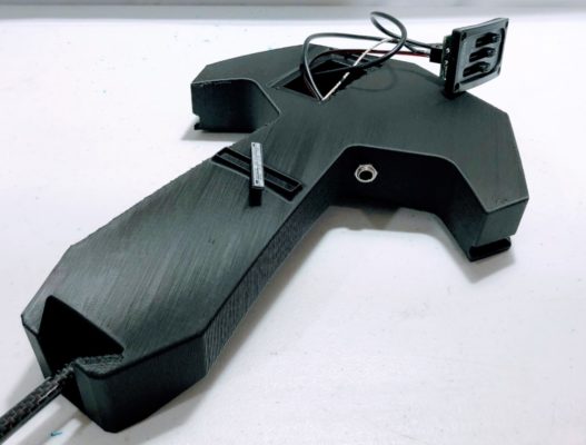
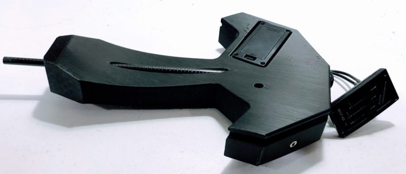
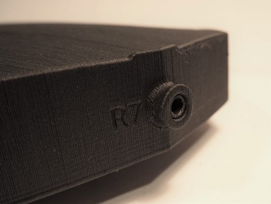
The latest electric bodies are not built for any specific pickup. Instead, they use a quick-disconnect connector to plug the pickup of choice into the electronics installed in the body.
HEY READ CAREFULLY! The images here are out-of-date!
The instructions here are for bodies in which the jack and potentiometer (volume control) are located next to each other on the bass side. The current design has the potentiomenter on the treble side, so there are two covers and the wire lengths are longer.
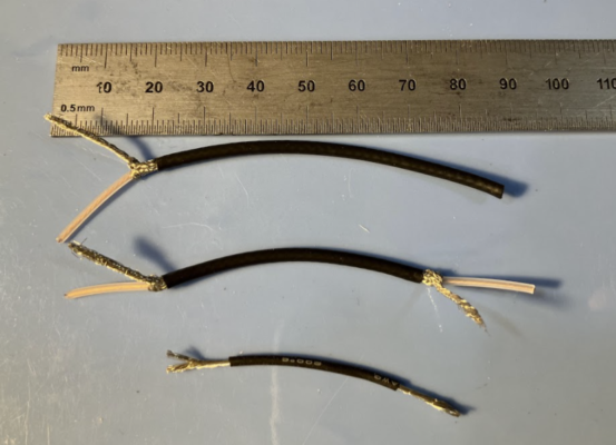
If you are building the version with the potentiometer on the treble side (two covers) then your wire lengths are:
- 180mm from jack to potentiometer, strip 15mm from either side
- 130mm from potentiometer to pickup connector, strip 15mm from one side
- Ground wire is the same, ~50mm
Here is what you need (wire lengths are spec’d for bass side pot):
- Alpha mini control pot (only this one will fit)
- Switchcraft 1/4 mono jack (or similar)
- A trimmed section of pin header for the quick disconnect (trim to 2 contacts)
- 2 sections of 80mm shielded wire (I use this)
- 1 section of 50mm ground wire (whatever you have is fine)
- Heat shrink tubing
The above parts are all included in an off-the-shelf parts kit that includes electronics.
I will not go into great detail about how to solder. If you are new to soldering, consider watching some youTube videos on proper technique, stripping and tinning wire, etc.
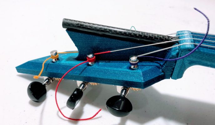
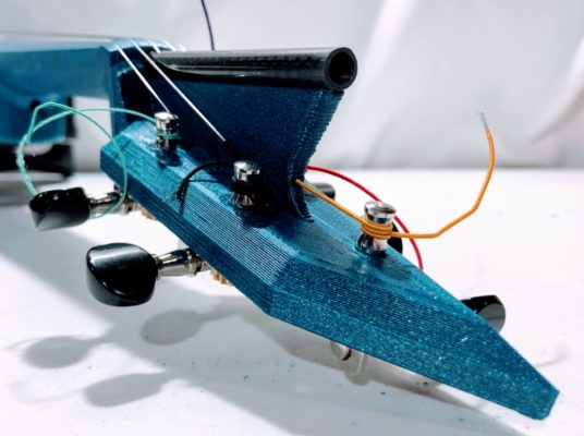
Here is the wiring diagram for the system:
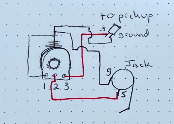
Where the pot is numbered 1, 2, 3, when viewed from above (the spinny part is up). G and S denote signal and ground.
The order in which you wire things is relatively unimportant. Below I show one way to do it. The acoustic-electric body is shown, but the steps are largely the same for the solid body.
First, prep your wires as shown (PHOTOS ARE FOR BASS SIDE POT).
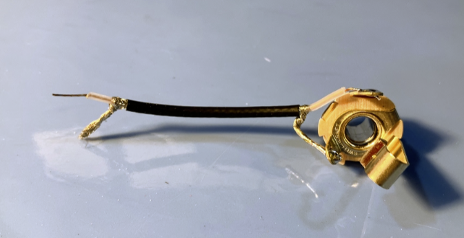
Take the wire with both ends prepped and solder it to the jack as shown.
Next, solder the unshielded wire to pot 1. When you solder anything to the pot, do it as quickly as you can, but don’t rush! It is possible to burn out the pot with too much heat, but I have never had this happen.
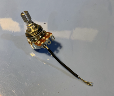
Now solder the signal wire from the jack to pot 2 and the signal from the pickup to pot 3 (right now it’s just a wire with one end prepped). Wrap the ground end of everything together with the wire from pot 1 as shown.
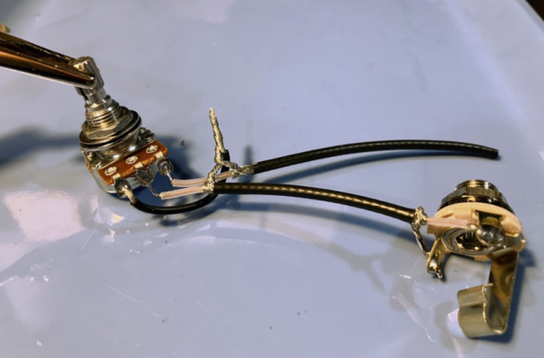
This last part can be tricky. You need to solder this bundle of ground wires to the back (or side) of the pot. I use a sanding block to thoroughly remove any finish from the metal. Tin the bundle all together. Now solder it to the back (or side) of the pot.
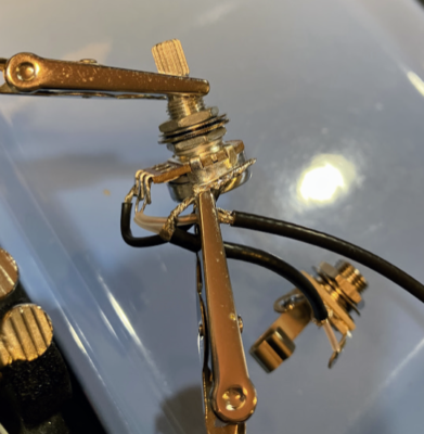
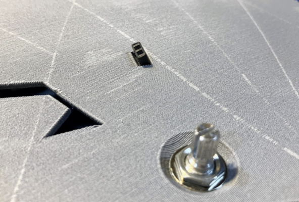
Now you’re ready to install the pot and jack to the fiddle body.
Route the loose wire (this will go to the pickup) through the rectangular hole in the body.
Pro Tip: Tie a piece of monofilament (fishing line) around the end of the wire and use that to pull it through the connector hole.
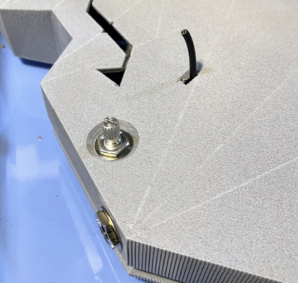
Cut the wire down if needed, you want to be able to pull it out about 3/4″. Now strip and prep the end, and solder to the female section of pin header. While not shown, I often use a small sheet of aluminum foil over the body to protect it from any bits of solder. I always solder the header so that the signal is towards the center of the instrument and ground is towards the edge. This way I always know how to orient my pickups on the other section of header.
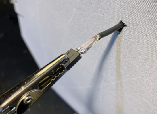
File the piece of header as needed to fit loosely in the body hole. Then fit a piece of heat-shrink tubing over the header and exposed wires and shrink it.
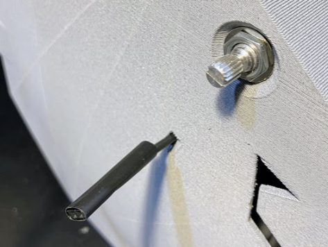
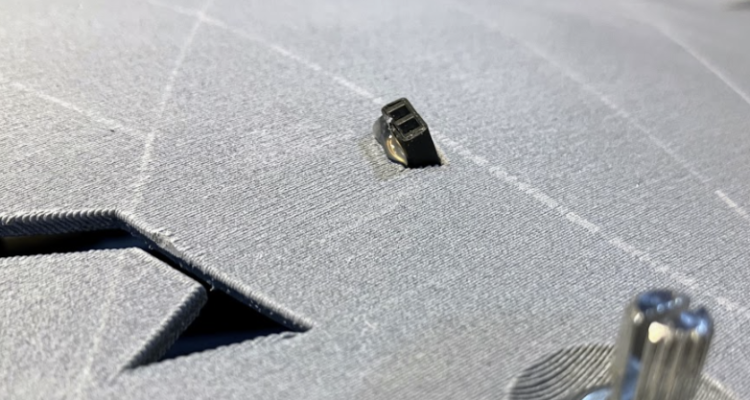
Now insert the heat-shrunk header into the body. It should fit snug. Carefully file or cut away body material if needed.
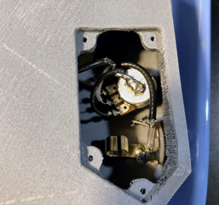
Secure with a dab of hot glue if you’d like to. I think it’s more professional to have this connector well secured.
You should be all set! You can tighten everything down and screw on the cover.
A Note About Plastic Screws (How Not to Fail)
Plastic screws are lovely little things that can be used over and over like magic, but there is a technique! If you are not careful, you will quickly strip out your plastic holes and you will think that the screws and the holes are dumb junk.
The technique is this:
If the screw is being inserted for the first time, just tighten it down. Great work. Don’t over-tighten! You aren’t fastening down car wheels or anything.
If the screw has already been inserted, and you are re-inserting it, you must NOT FORM NEW THREADS. So you have to find the threads formed from previous insertions. If you re-use the threads, you can use the hole over and over.
To find the threads, insert the screw and gently turn it backwards (counterclockwise). Apply a light pressure. Feel for a little ‘bump’ feeling. That ‘bump’ is the screw seating itself into the thread. Stop when you feel the bump, and then turn clockwise to insert the screw. With some practice this is very easy, and is a skill you will use for the rest of your life to insert tiny plastic screws into things.
It’s time to install the CV-210E pickup into the body. If you are building an electric with a different pickup, then this step does not apply to you.
The CV-210 has the following parts:
- Control Board (with sliders)
- Battery Compartment
- Bar Pickup (goes under bridge)
- 1/4″ Jack and Nut (your main jack)
- 1/8″ Jack and Nut (headphone jack)
- Extra bits (you don’t need them)
The installation process is very similar between the electric-acoustic and the solid body electric.
First, install the bar pickup. For the solid body electric, run the sensor wire along the truss rod cutout, then install the truss rod to hold the wire in place.
Let that bar float, don’t worry about it. Go ahead and plug the micro plug into the control board to keep it in place.
Install the 1/4″ and 1/8″ jacks. Plug them in to the control board.
Install the battery compartment, route the power wire through the body and plug it in to the control board.
Screw down the battery compartment with the provided screws. Here’s what it should look like now:
Now, for the solid body, you have to do something a bit tricky. I don’t have great pictures for this yet…
Unplug the pickup wire from the control board. Make a loop in the wire and pass the loop through the random hole in the body. Pull out excess wire, you want it to stay looped and loose. Plug it back in. Now you can screw down the control board.
Before you string the instrument, stick a battery in and make sure the pickup is making sound. These pickups are not high quality, and some of the connectors can be touchy. That’s why we made that loop in the sensor wire — because you might have to fuss with the plug.
Once you get it all working, you can stuff the wire back into the body. If you find that the connector cuts out you might need to leave a small loop out to relieve stress on the connectors.
Whatever you do — the last step is screwing down the main board.
Medium and long necks (for viola or 5-string) are printed in two parts. You need to bolt them together, and they are designed to use heat press inserts. These are amazing little inserts that everyone should learn to use, because they are awesome.
First, prep the parts by filing flat the mating surfaces.
In the image, below, the parts to the right are prepped and ready, and the parts to the left are not.
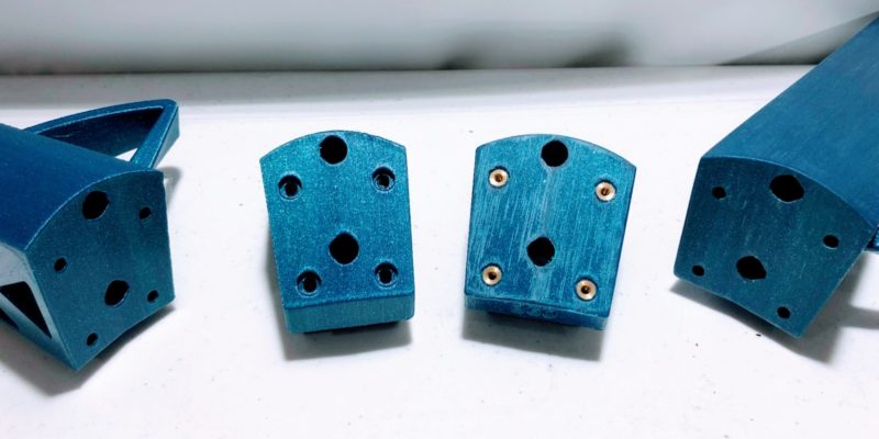
After filing the surfaces mostly flat you are ready to install the inserts. If you want more detailed instructions, do an internet or YouTube search for “install heat press inserts.”
The holes in the neck joint part should not require any prep. Simply heat your soldering iron to low-medium heat (mine is set to 450F), place the insert on the tip of the iron, and gently press into the holes of the neck joint part. Be careful to align the insert perpendicular to the face, and note that they are angled out slightly. Once the insert is pressed in so that it is sub-flush, remove the iron.
Allow the inserts to cool COMPLETELY before you join the two parts.
Once cool, fasten the neck and neck joint together with the provided M3 socket heads. Before you tighten down the bolts, insert both the neck truss and body truss into the truss holes of the neck. Make sure it all fits, then tighten down with the trusses inserted.
DO NOT OVERTIGHTEN.
Note that when the bolts are tightened, they are trying to pull the threaded inserts out the way that they are installed. The flange on the insert is useless. Don’t worry. When correctly installed, these inserts are strong enough, but do not overtighten. They should be very snug, but not overly tight.
You will need to tighten these bolts down every few days for a week or two to make sure they are tight after the plastic compresses somewhat. Eventually it should all settle and stay tight. If yours does not, you might have some issue.
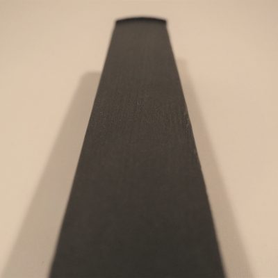
Run the carbon fiber tube through both truss rod holes in the neck. It should pass all the way through with moderate resistance. If you are unable to push the rod through by hand, you will need to open up the rod paths in the printed part. A 5/16″ drill bit is a good size for this.
For built-in endpin bodies, check the fit of the truss rod. Run the rod through either end of the body. The rod should pass through quite easily. If it is too difficult, adjust the printed part.
Now that we know that all parts fit together well, it’s time to put things together!
I am not going to give instructions for setting up traditional friction pegs (wood or printed) or geared planetary pegs. While setting these up is not crazy difficult, it does require specialized tools (a pegbox reaming tool and maybe a peg shaver). And then even with the tools it takes some experience to get it dialed in. If you are using one of these peg options, search youTube for good installation info.
A note about Perfection Pegs:
Just be really careful with your reamer. Take it really slow. Once the hole is too big, there is not a lot you can do. Use good glue. Gorilla Glue original formula is great.
Graphtech Tune-a-lele Tuners
Actually, these tuners are not reliable and may break. If you still use them (I do on some builds) I would recommend keeping extras in your case.
Open up the tuner box and take out the tuners, bushings, and screws. You may set aside or discard the bushings, you do not need them. So now you should have just the tuners and screws.
Your pegbox probably printed a bit tight for the tuners. See if they insert into their holes, but don’t force them. If they insert and can spin in the holes with light friction — great! If they don’t insert, or are too tight, you need to drill out the holes with a 7/32″ drill bit. You might need to wiggle it around a bit to widen the holes, but you want the tuner to fit snug in the hole, so don’t drill out too much.
The stock screws work OK, but they are brittle. If the screws take very much force to insert and tighten, drill out the screw hole with a 1/16″ bit, or a little larger. If they are too tight, the screws will break while you screw them in or out and then that’s a bummer.
The tuner casing is also fragile! So don’t overtighten. You really just need the screws to be just barely snug to the casing. They just prevent rotation, they don’t need to clamp down hard.
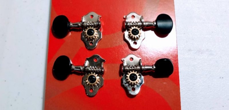
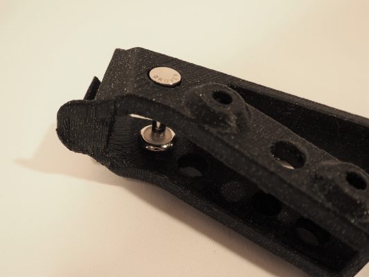
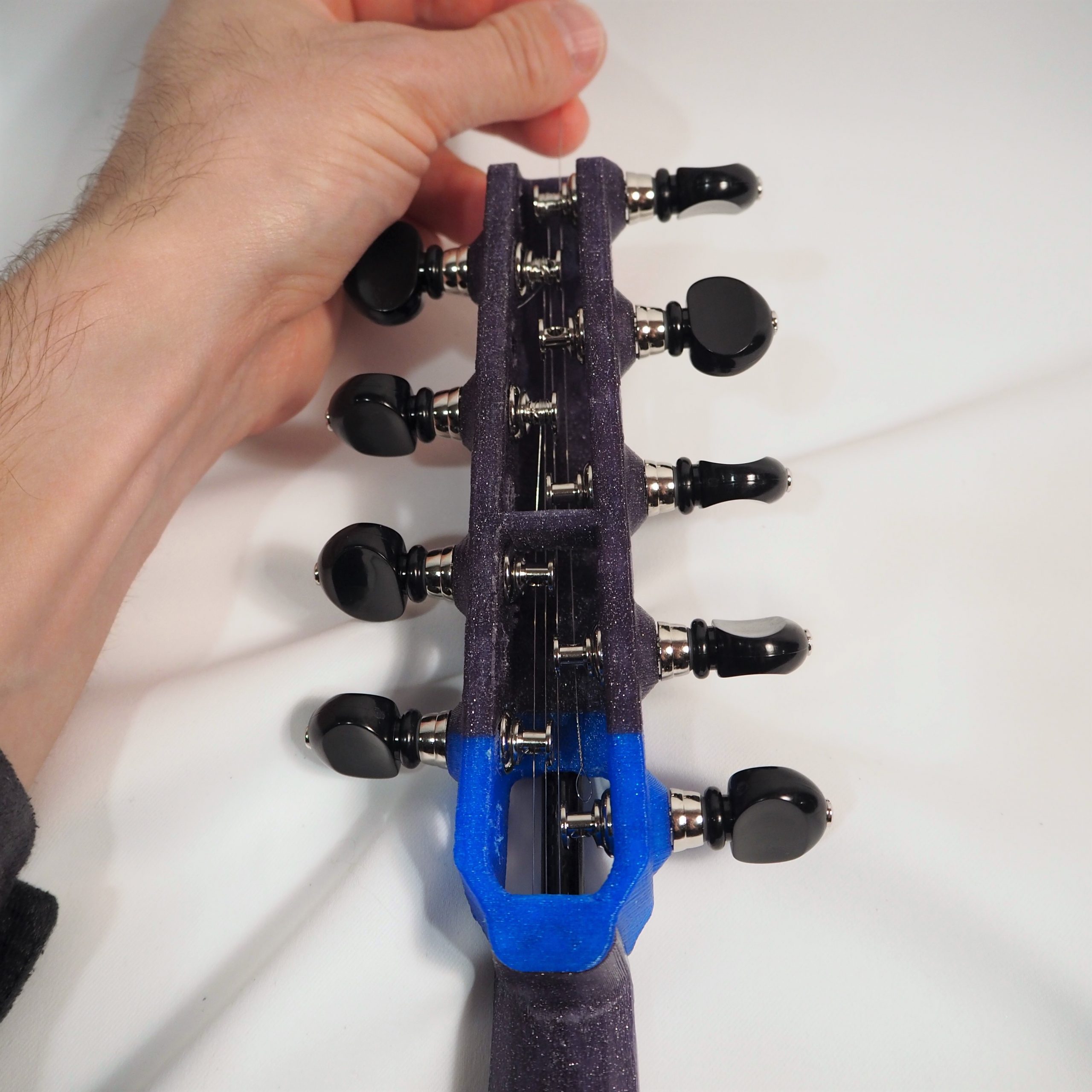
Grover Geared Uke Tuners
First you need to disassemble two of the tuners and reverse their direction. If you bought a kit from me, I have already done this. You lucky dog.
You want all of the tuners to tighten the string by rotating away from the player. For these uke pegs two of them are correct, and two need to be reversed. Find the two that don’t turn right.
Start by removing the bolt shown, below. Note that both of these tuners need to be reversed.
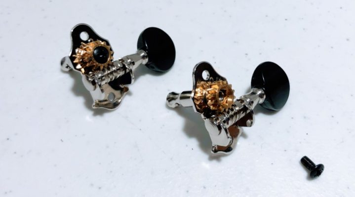
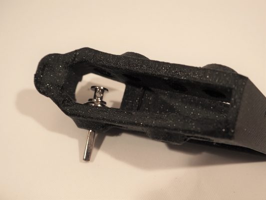
Now pull apart the gear mechanism.
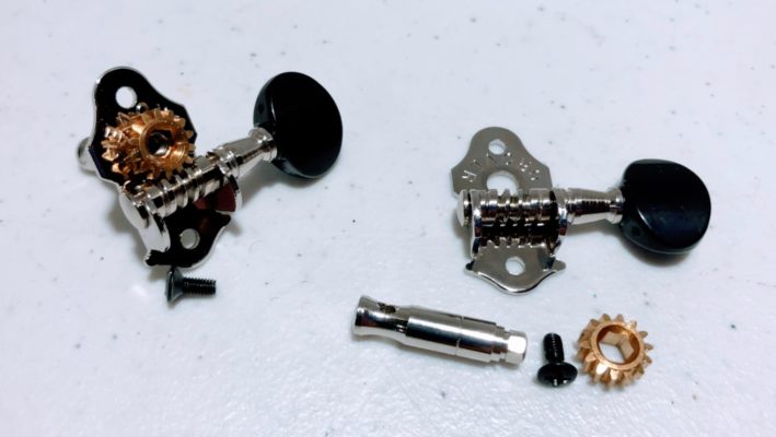
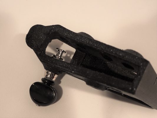
Next, pop out the tuner handle (with the black knob). Flip it around and pop it back in. The one to the right, below, has been flipped.
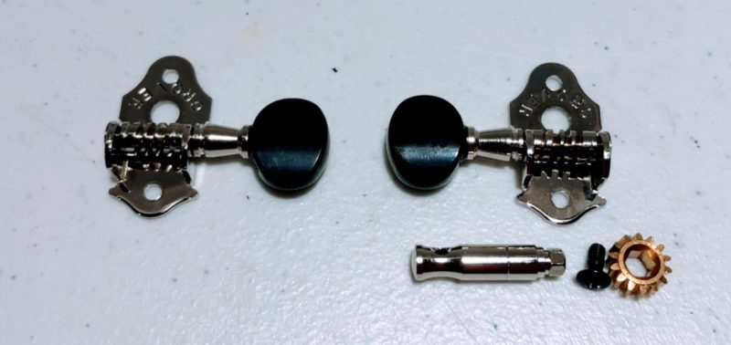
Now reinstall the gear mechanism and tighten the screw back down. You should now have 4 (or 5) tuners ready.
Now let’s prep the pegbox for the tuners.
I no longer use the tuner bushings. They are heavy and can be very difficult to install. Discard them.
See if the tuner shaft fits into the holes. If it is too tight, chase the holes with a drill bit (7/32) to loosen the fit just a tiny bit.
Also drill out the screw holes with a #50 (.07″ / 1.78mm) bit. I use a depth stop bit from StewMac, but you can just be careful not to go too far.
If the screw holes are too small the screws may break during install and you may need to start over with a new part.
If your screw holes are too big (printer settings vary considerably), fill with epoxy, let cure, and then drill to size.
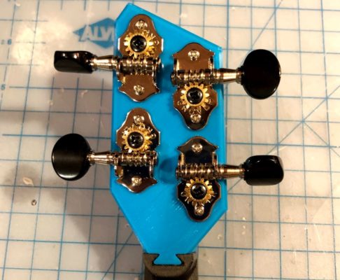
Once your holes are all the right size, go ahead and stick the tuners on and screw them down. As long as all the screw holes line up and the tuner handles stick out so you can turn them — you are good!
Grover 6-series Tuners
These are not really a great tuner option. They simply don’t stay in tune! However, they work OK and allow a classic violin look without having to set up pegs.
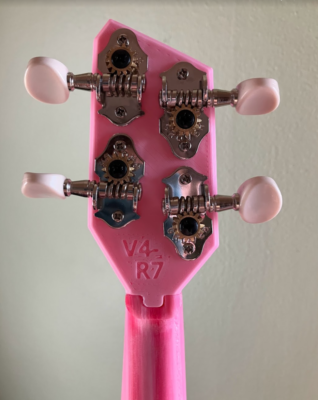
Start by installing the ukelele tuners to the pegbox. These are installed as shown in the pictures, below.
Tighten down the tuners with a screwdriver, and tighten them very firmly! They will settle over time, so check these and re-tighten as they loosen up. After a week or two (if you’ve been tightening them regularly) they will settle and won’t need constant tightening. If you do not tighten them, they will slip and tuning your fiddle will be impossible.
Even if you do tighten them, though, they may slip. They tend to have a ‘happy place’ where they like to sit, and if that happy place is out of tune…
Pro tip: Keep a small screwdriver in your violin case!
Here’s what they look like installed on the 4-string pegbox.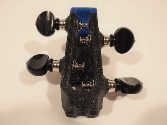
The neck is the only part that requires significant sanding. How much you sand is up to you. A smooth fingerboard is nicer to play on than one with noticeable layer lines. I typically spend 20 minutes sanding a neck for myself. If I am building a fiddle for a customer, I’ll spend an hour.
While sanding, wear a dust mask to protect from sanding dust. I also use a HEPA vacuum system to pull dust away and out of the air.
Sand or otherwise smooth out the layers on the underside of the neck as well. You don’t want any loose strings of plastic to poke you as you move up and down the neck.
Here’s my smoothing process:
- Use a large file (or a combination of file and scraper) to do the large smoothing on the fingerboard and hand contact areas on the underside of the neck. File or scrape thoroughly until the surfaces are even.
- Once filed evenly, sand out the file marks with the 100 grit sanding block.
- Once sanded evenly, sand thoroughly with the 220 grit sanding block.
- Allow to dry (if wet sanding) and look for file marks or rough patches where you did not fully sand. Go back and repeat step 3 or steps 2 and 3 on these spots.
- Sand again with 300+ grit. You should start to see some polish.
- Once you are satisfied, rub/polish with a very light coating of mineral oil to restore surface finish.
Here’s a neck that I feel is smooth enough. It’s hard to tell by the picture. It’s pretty smooth, but it could be smoother. Some of what looks like texture is the glitter melted in with the plastic. (It’s Proto-Pasta’s black glitter filament.)
It does work to coat the neck with some sort of coating. I have used epoxy. The epoxy coating I used did wear significantly faster than PLA, though, so I am unsatisfied with this as an option and prefer plain sanded PLA. I have not yet seen a neck with significant wear. If you have a neck that has worn down from use, please get in touch and send me pics!
I recommend using the 3D printed chin rest. It looks awesome, it’s 3D printed, and most players are happy with the surface finish. If you would prefer to use a wooden chin rest, you can do that! Most Guarneri style chin rests will fit. Just clamp it on there and center it as needed to avoid contact with the tailpiece once you assemble the instrument.
Setting up the 3D printed chin rest
You will want to thoroughly file and sand the player-contact areas of the chin rest. The process is just like with the neck.
- Start with a file and smooth out as much as possible on the player facing side of the rest.
- Then move to 100 grit sanding block and smooth the filed surfaces as well as the top of the chin rest.
- Finish with 200 grit and then do a mineral oil rub to restore the surface finish.
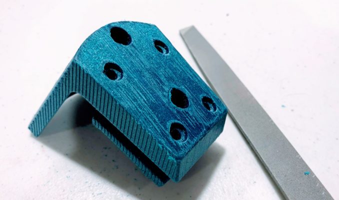
Once it is finished to your satisfaction, press M3 heat press inserts into the chin rest holes shown, below.
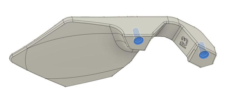
Allow to cool. Now you can bolt the chin rest to the body using two M3x45 flat head cap screws.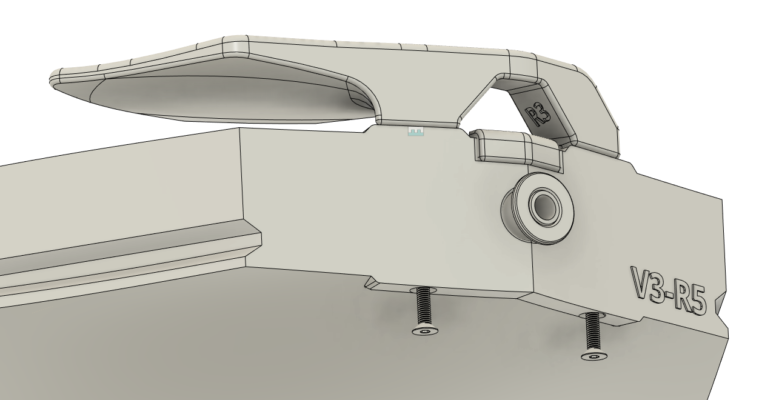
These bolts will need to be tightened after a few days, so check them and tighten as needed. Do not overtighten, just finger tight with the short end of an allen wrench.
The parts all fit, your neck is sanded, and your tuners are installed — it’s time to put it all together!
V4/V3 Body/Neck Assembly
For V3 and V4 builds, you can insert the truss to the body, then slide the neck onto the truss, push it to the body, and install the four M3x10 socket head cap screws. Tighten carefully and DO NOT OVERTIGHTEN.
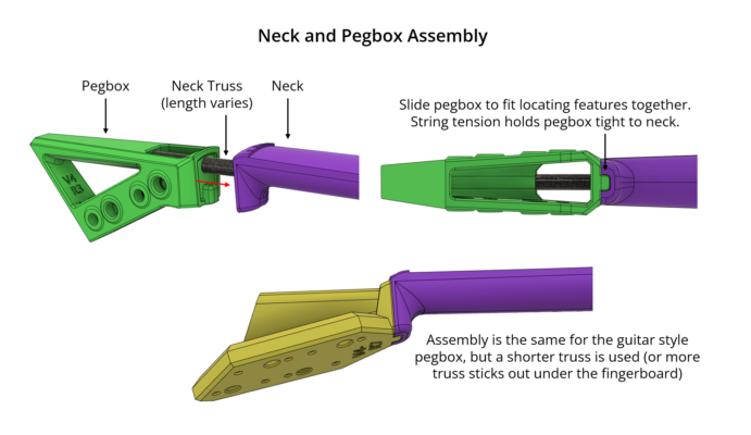
V4 Pegbox Assembly
If you have already fit these parts, then this should be incredibly easy. Slide the neck truss into the neck, then slide the pegbox onto the truss.
V2 Body/Neck Assembly
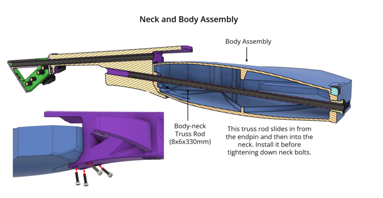
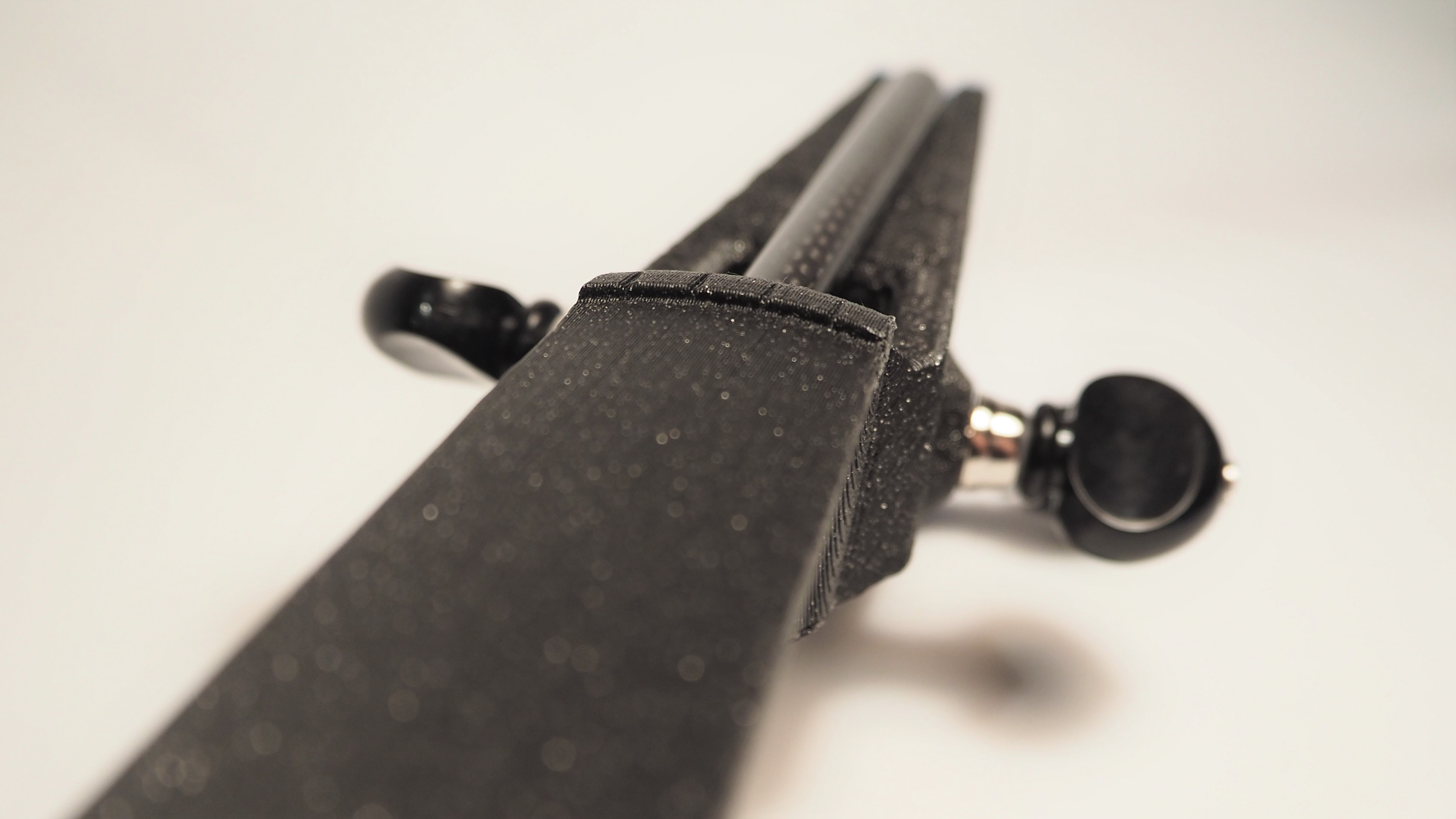
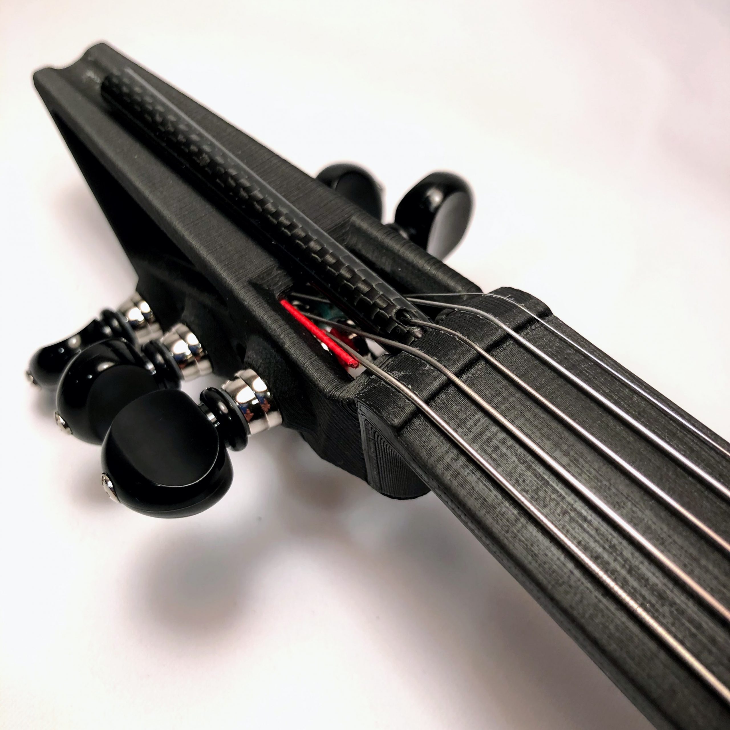
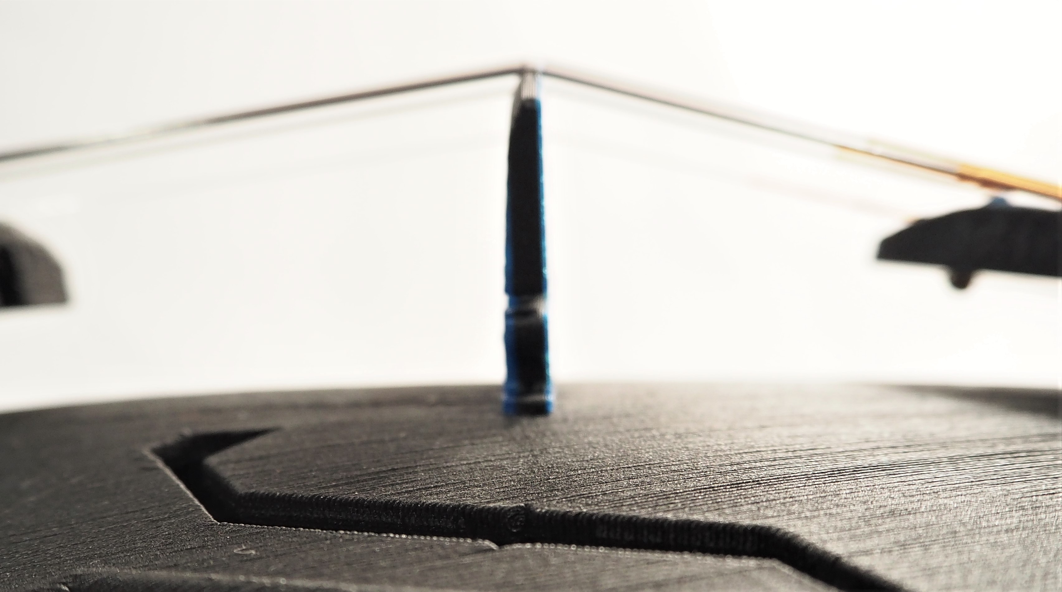
 Slide the neck and body together. Install the truss rod from the endpin of the body (by the chin area). As you slide the rod in, look through the inside of the tube to see where the other hole is. Aim for that, then push the rod through into the neck. Push it until it is just past flush with the endpin, as shown. You don’t want the carbon fiber rod to stick out and irritate your skin.
V3/V2 Pegbox Assembly
Install the neck truss rod. Push it through from the pegbox side. You may push it all the way to the end of the fingerboard, or you may leave it extending further over the pegbox.
Slide the pegbox into place and it will seat on the truss rod.
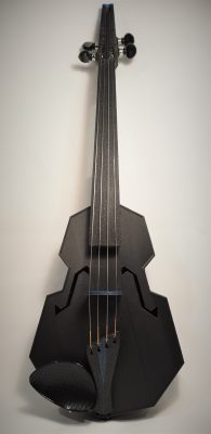
Here’s what your fiddle should look like, and the parts shown are the ones we will need to finish the assembly. Congratulations — you are about halfway done with your assembly! Unless you’re building a Hardanger, in which case you have far too many strings to deal with…
See next step for 5-String details.
You are about to start the finishing steps! This last part is very important, though, and you’ll need your patience. If you need to take a break, do it now.
From here on, make only small changes to your parts. The string grooves on the nut and bridge are critically important, and you don’t want them to be too deep. Also, a poorly shaped nut groove will cause your strings to pinch and break, especially on steel strings like a set of Helicores. Take it slow!
 First, prepare the bridge by lightly filing the feet so that they will fully contact the top plate of the violin. You don’t want it to only touch on the edges, which is usually how it would sit right off the printer.
You can lightly file the string grooves on the bridge, but don’t go crazy! You want as shallow a groove as you possibly need to hold the strings securely, and you may be surprised how well they will hold. Smooth the grooves as needed with a bit of sandpaper. Sharp edges will damage strings — keep that in mind.
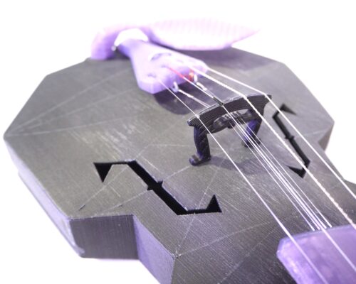
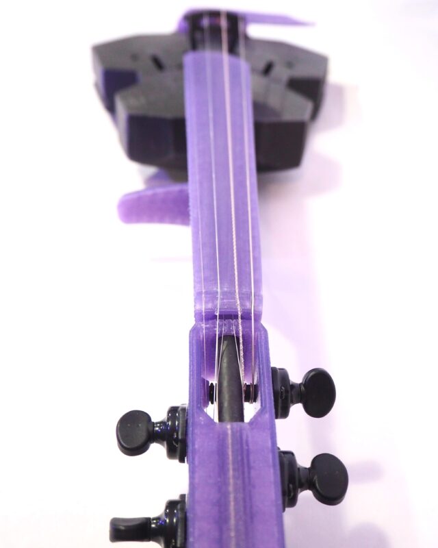
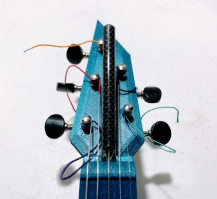
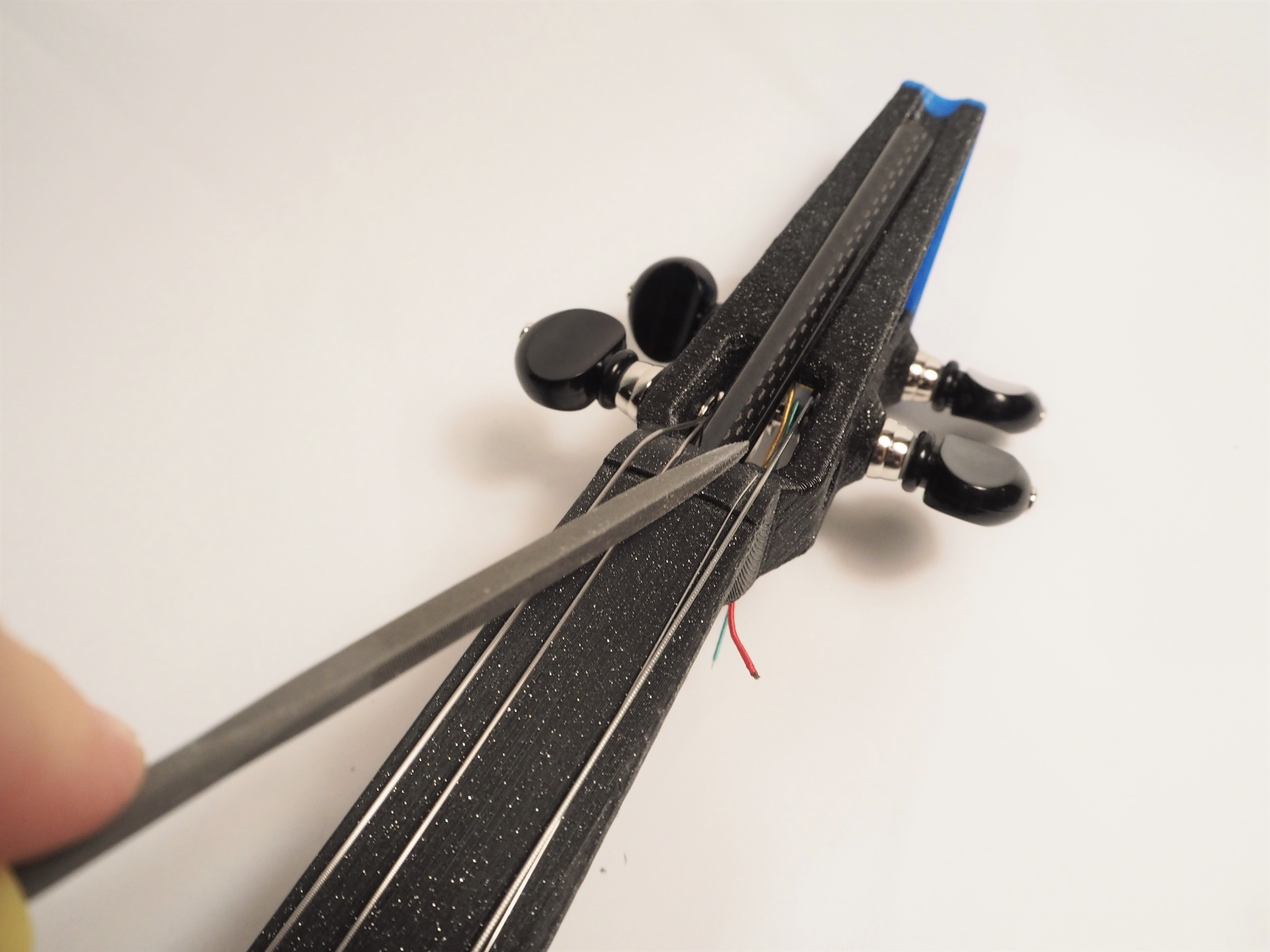
Also lightly file the nut grooves. File in angles for the D and A strings to go to either side of the truss rod. Look carefully at the images, below. Make light grooves! You can always file more later.
Above is as printed. Grooves are in the right place, but not deep enough, and need to be filed to carry the string all the way through the nut to the tuner side.
Grooves have been lightly filed, above.
Grooves are fully filed and for the D and A string they channel the strings around the truss rods. The D bend is a little sharp here, but I didn’t know that back then.
Hardanger
Follow the steps, above for the Hardanger as well. If needed, gently tidy up the understring grooves with a file. Be sure to make small changes! You will go back and adjust after strings are installed.
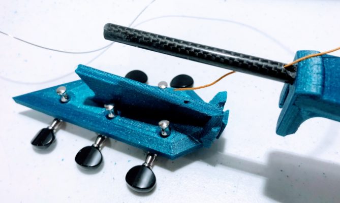
On the five string you have two options for your D-string path. You can either file a deep angled path to send the string around the truss rod, or you can drill through the truss rod using the printed truss drill jig included with the design files. I recommend drilling the carbon rod. Getting the D string around the rod while keeping an even spacing between strings can be difficult, and a sharp bend like this could cause damage to the string. Both options are shown, below. Also be sure to use a round file to get a good groove for your C string. If it pinches the string, it will break. I have broken several Helicore C strings, and they are expensive!
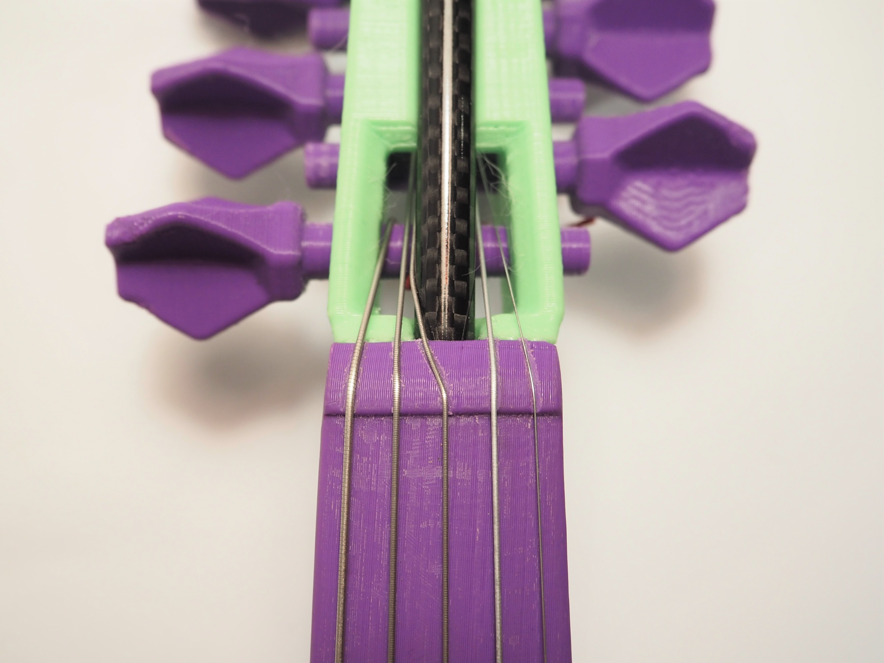
The D string can be routed around the truss as shown, above.
Or drill a hole through the truss using the printed jig.
There are a few different versions of the truss drill jig. It is still a work in progress, so if what is shown here does not match your jig — well, hopefully you have an improved version!
The latest jig has two positions for the truss rod. You may either insert the rod so that it is flush with the end of the jig, as shown below.
Or you may insert the jig so that it is flush with the inner cutout, as shown below.
Which is correct depends on too many factors for me to say which you should do. I would recommend inserting to one depth, marking the hole locations, and then see how that positions the holes for your pegbox/neck combination. Then repeat for the other depth.
You want the D string to pass cleanly through the truss rod without rubbing on the drilled out edges.
So whichever depth gets the holes positioned correctly, and the truss rod does not stick out awkwardly from the pegbox, that’s the right one.
To drill the truss rod simply clamp the whole assembly in a vice and drill through the guide hole with a 3/32 bit. Then release the vice, flip the assembly, and drill the other side.
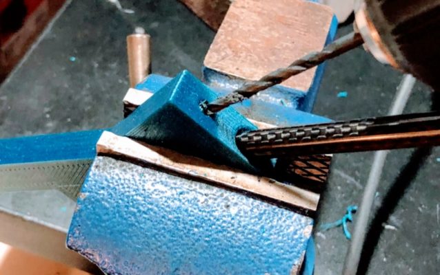
Pro tip: drilling these holes can be tricky. If you drill the wrong depth, or if the holes are too messy, just flip the truss rod and try again. Your ‘wrong’ holes will be hidden in the neck and the truss will still work just fine.
Most V3 bodies use a newer saddle design, and the instructions for installing that are in an earlier step.
The saddle is the part that sets the height of the tailpiece. The tailgut (nylon cord) exits the tailpiece, goes over the saddle, and then hooks around the end pin. Early bodies, V1 and V2, had the saddle built in to the body all as one part, like this:
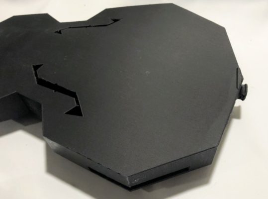
More recent bodies (V2-R9 and later for 4-string) are designed without a built-in saddle. You must print the saddle as a separate part and install it to the body. In the image, below, the body to the left has no saddle (and needs one) while the body to the right has had the saddle glued on.
You may glue it on if you’d like, I would recommend a semi-permanent glue such as E6000, or you may simply stick it on and let string tension hold it. If you want to glue it, do so now. Not gluing? You can put the saddle on when you string the instrument.
Based on experience, I no longer recommend attaching understrings to the tailpiece itself. Instead, I recommend using the ‘Understring’ body and attaching the understrings to wire that is mounted directly to the body.
In addition, I recommend attaching the tailpiece using a ‘normal’ nylon tailgut. While a hardanger fiddle tailpiece is typically wired in place, I find that this technique places additional stress on the tailpiece and is generally not necessary to provide enough clearance for the understrings.
Here are photos of a hardanger body set up in this fashion.
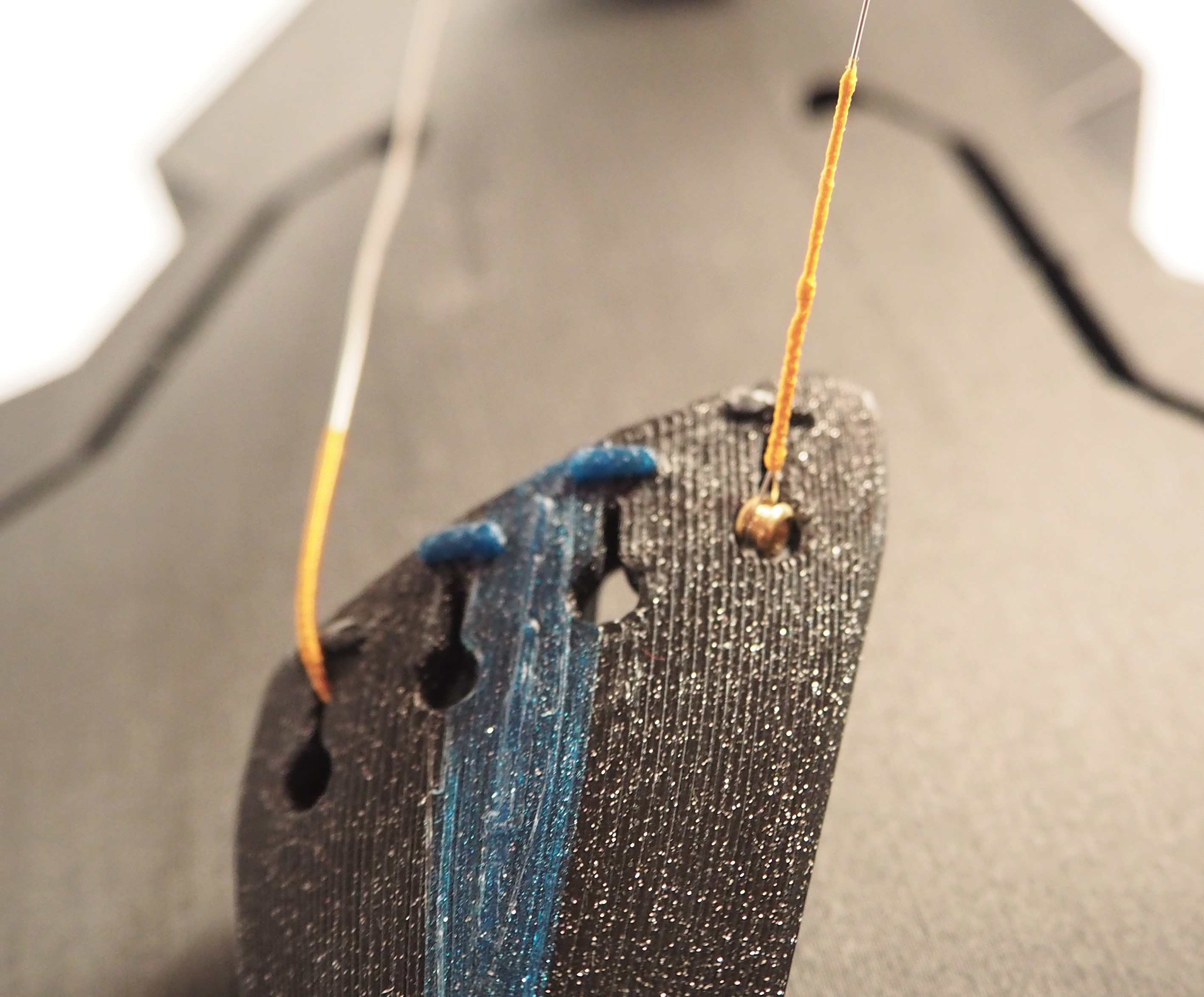
Let’s get a closer look at the understring wire.
To mount this wire, simply bend it into a U shape and insert into the two holes from the endpin. Bend the wire and cut as needed. Press the back of the wire (underneath the saddle) to lay against the body as much as possible.
I recommend installing the endpin and saddle before the understring wire, but this order is not important.
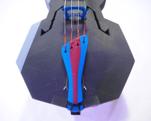
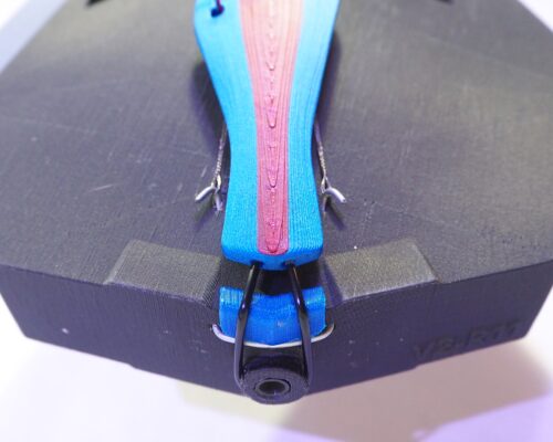
Whether you are using a printed tailpiece or a purchased tailpiece, the installation process is about the same. Install the adjustable tailgut, which is usually a nylon strand with threaded ends and brass fittings. 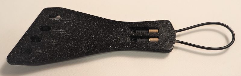
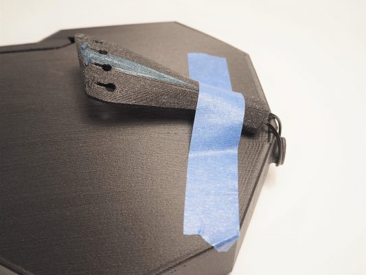 Adjust the tailgut until the tailpiece, when looped around the endpin and pulled tight, sits comfortable above the body, with the tailgut running smoothly over the edge of the body. Tape it down with some painter’s tape to keep it in place until you string the instrument.
Stringing a Hardanger fiddle is a meditative practice that will teach you patience and refresh your vocabulary of obscenities. Let me offer some tips that have helped me.
If you haven’t already, read through David Golber’s article, What You Should Know About the Hardanger Fiddle. Note that I do not follow the understring peg pattern shown here, but you may!
Understrings are generally strung in one of two patterns. I need to find a good graphic for this. I string mine in the same pattern as the playing strings, with the highest directly behind the “A” peg, and the lowest directly behind the “D” peg. While some Hardanger fiddles are set up this way, it is not the most common pattern. It occurs to me that when strung in the standard Telemark pattern shown in the article linked, above, tension is more evenly distributed along the neck.
Note: understrings that are specifically Hardanger understrings WILL PROBABLY BE TOO SHORT. I recommend using single guitar strings for your understrings. They are very long. I have also used light tension mandolin E strings in a pinch.
In the instructions, below, the understrings are strung directly to the tailpiece. This is no longer recommended. The process for installing understrings to wire mounted to the body is the same, so these instructions are left as-is.
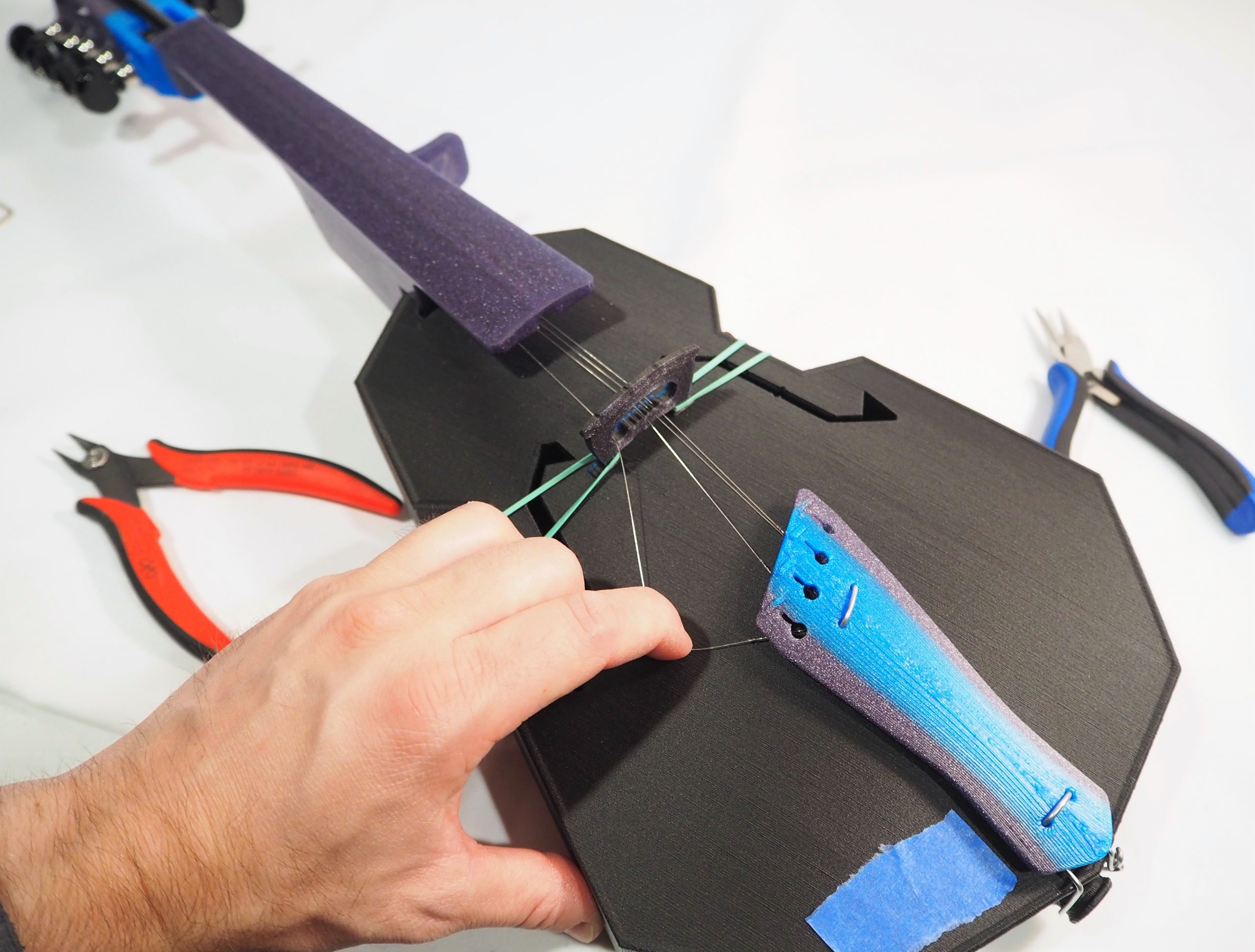
You will need the tools shown, below. A pair of snips to trim strings, needle-nose pliers to grab strings, a small allen key or screwdriver to move strings around, and tape to tape strings down to the body. Put on some good music, too.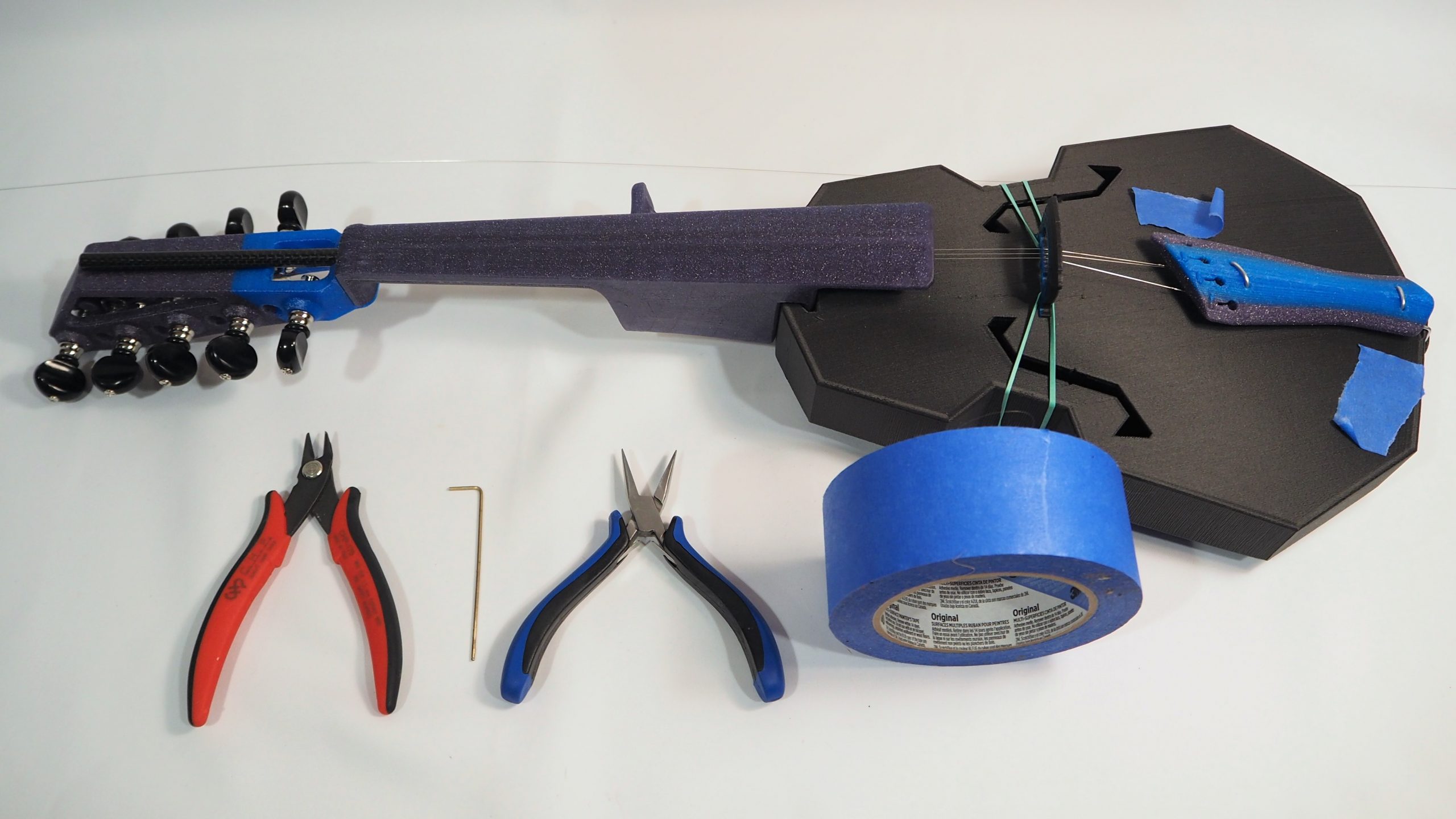
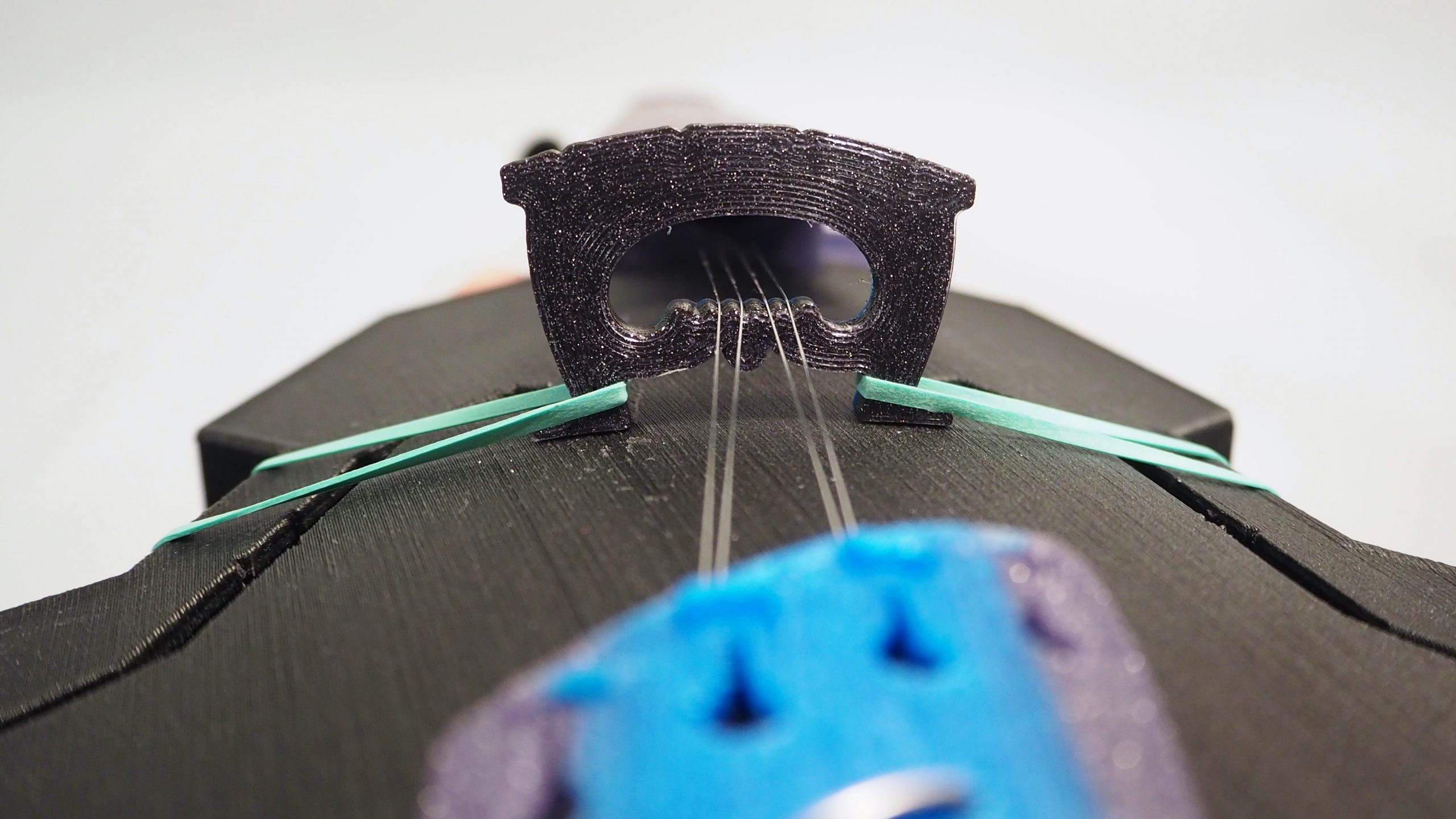
Secure your bridge with rubber bands on the feet wrapped around the body as shown.
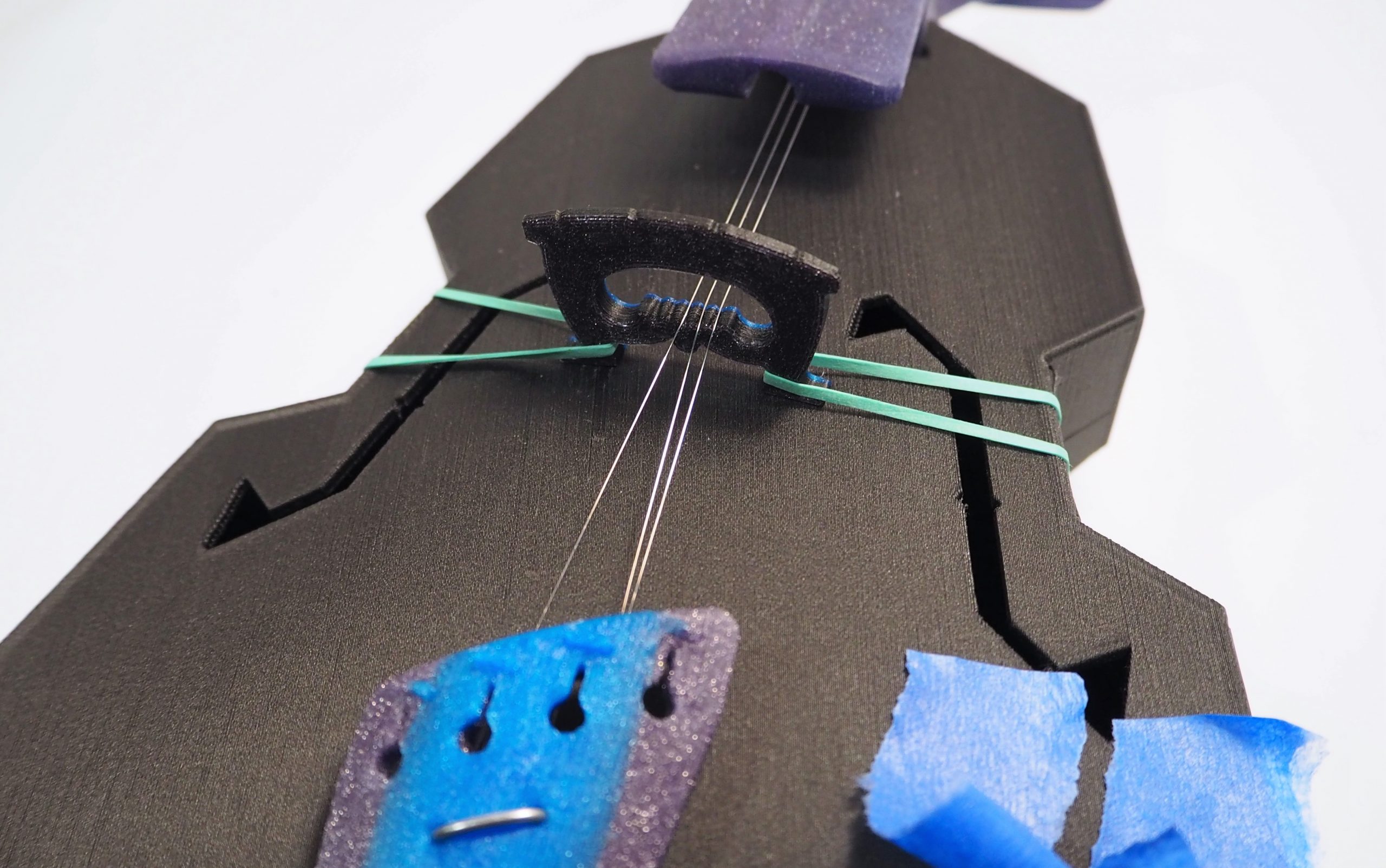
As you’re stringing, hook the understrings to the tailpiece hooks such that they do not cross to cut down on buzzing. For the first two strings, you’ll need to send the first one down the neck channel and tape it to the body (so it doesn’t pop loose from the tuner). While it’s taped, send the second string. This one you can hook on to the tailpiece and bring to slight tension. Then hook the first and bring to slight tension.
Otherwise, send strings down the channel and bring to slight tension one string at a time. If your understrings have ball ends, remove the ball with pliers. Send the loop ends down the neck from pegbox to tailpiece.
Once the string is through the neck, hook it to the tailpiece. Use your finger to hold tension in the string while you tighten the tuner. If the string unravels and pops off the tuner, you may need to start over.
Don’t hesitate to tape strings down while you’re working! Having them pop off the tuner is a pain.
Traditional Hardanger fiddles can have four or five understrings. I have a lot of extra tuners, so I typically string five strings. Four is easier to manage. If you are unsure, string four.
Without the playing strings, the understrings should enter the neck channel about midway between the top and bottom of the channel. As you add the playing strings and bring them to tension the instrument will bend and your understrings will get closer to the top of the channel. Generally speaking, you want them to be as close to the top as possible without touching. Aim to allow 2mm clearance.
You can make small adjustments to the understring height by filing down the bridge notches. You can also adjust at the nut, but start by adjusting the bridge.
The Hardanger files now have three bridges: short, medium, and tall. I typically build with the medium bridge and file down the understring notches slightly. All build come out a bit different!
Here are some photos of the most up-to-date design.
Notice that the understrings are now much closer to the playing strings, this is good!
Note also that you must be careful to set up your understrings and playing strings so that the playing strings do not rub on the understings. A steel understring will very efficiently destroy an expensive gut string.
With some gentle shaping of the nut and bridge complete, you can now put on your strings. I usually string the G and E first to hold the bridge centered.
Make sure your strings are fully seated while tightening!
 Start with the G string. Send the ball end through the circular opening in the tailpiece. Then pass the string over the nut and into the pegbox. Stick it down into the hole that goes through the tuner shaft, and tighten the string by turning the tuner away from the player. This is counter-clockwise for G and D tuners, and clockwise for A and E. While it seems odd, this is standard, and ensures that your strings will come off of the top of the tuner shafts.
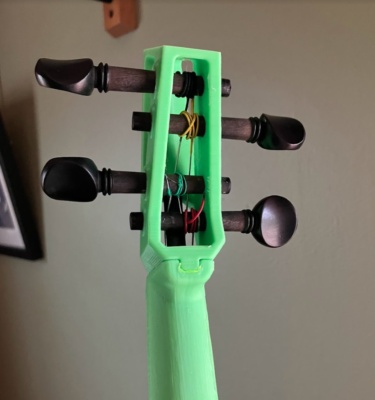
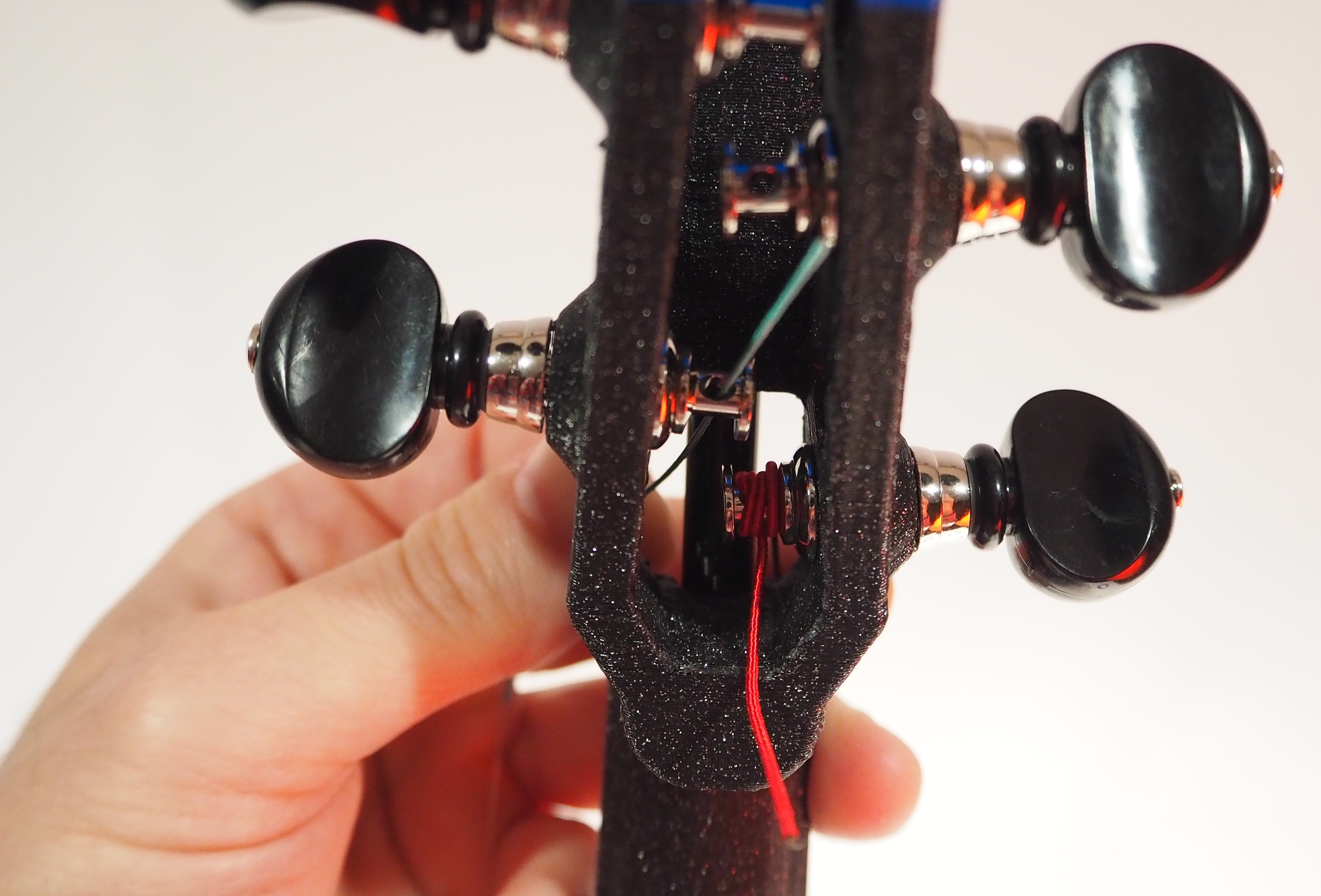
For the Tune-a-lele tuners, the hole in the tuner shaft is kind of in the wrong place. You’ll want to start the string in that hole, do one winding on the inside of the hole, and then move the string to the outside of the hole as you continue winding. Here’s a photo of what a strung tune-a-lele pegbox looks like.
[photo of tune-a-lele strung pegbox]For the geared tuners — the process is similar, but easier. You don’t have to thread the strings into the pegbox, and the tuner shaft is vertical. You want the strings to come off of the inside of the tuner shafts.
Once all strings are installed, gently begin to bring them up to full tension. You don’t need to get them all in tune, but get them close. As you tighten the strings, frequently check the bridge alignment and adjust as needed. You want the bridge to sit perpendicular to the top plate, and in line with the little hash marks of the F holes.
Stringing a Modular Fiddle is a little different than a traditional violin, but much of it is also more or less the same. Watch this eHow video, below, if you want to learn more about stringing a violin.
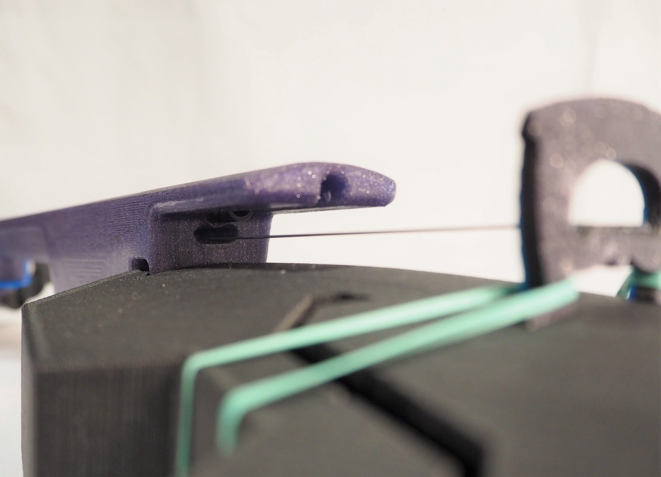
First, check the height of the strings at the nut. You should have about 0.5mm under each string (a little less at the E, and a bit more at the G). One rule of thumb is to allow half the string thickness between string and fingerboard at the nut. Nowadays I can usually feel when I have my strings where I like them, but a business card also makes a good indicator! Mine is 0.4mm thick.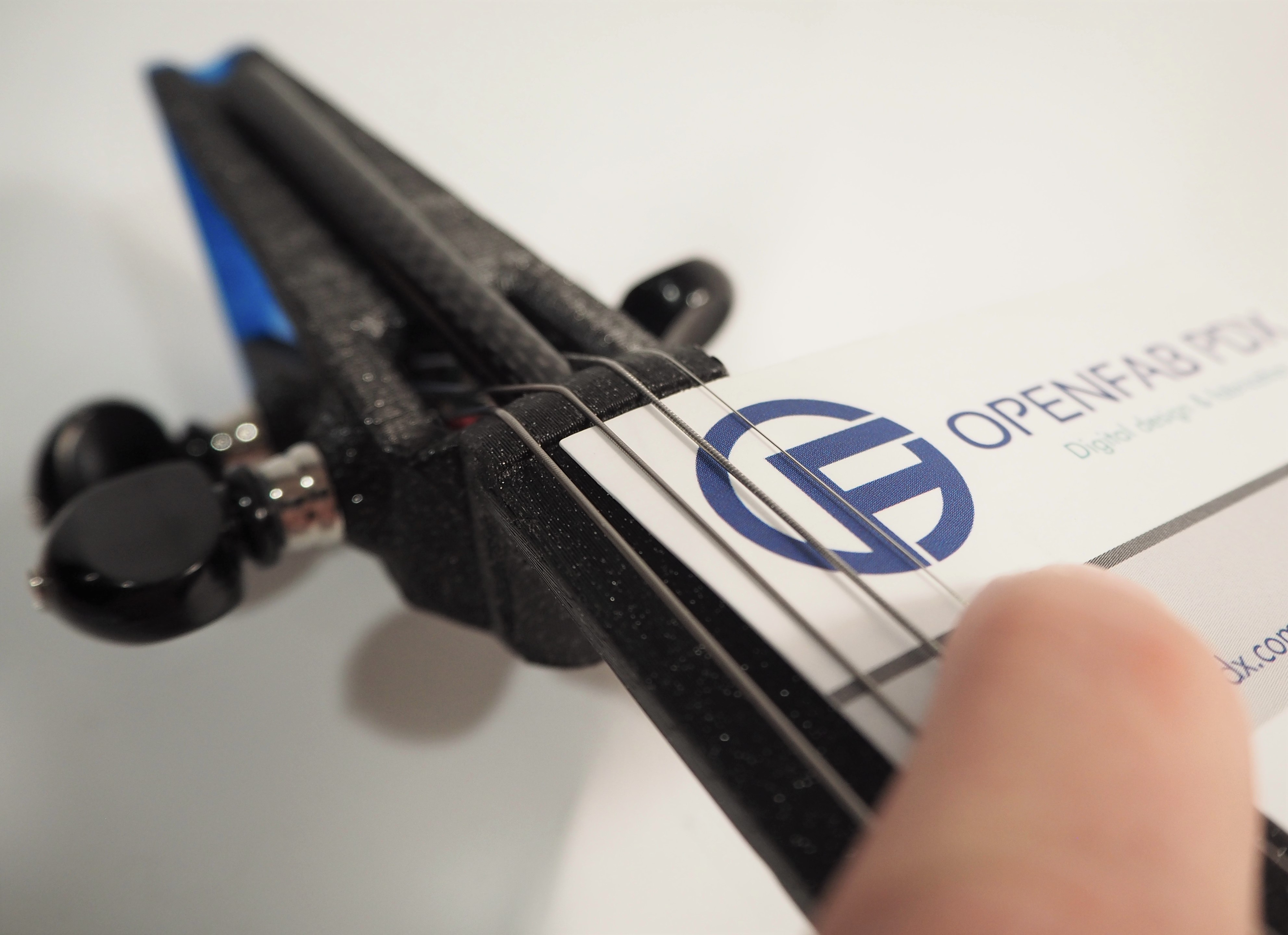
To adjust the nut height, loosen the string that you wish to adjust. Loosen until you can pick it up and move it over and out of the way. With the string out of the way, carefully file the nut grooves deeper. I use a combination of my triangular file to get the depth, and then a round file to get a good profile on the groove and to avoid pinching the strings.
After you’ve adjusted your nut heights, and brought the instrument back close to tune, it’s time to check the string height at the end of the fingerboard. You want them to be about 3.5mm for the E string, 5.5mm for the G, and somewhere in-between for the D and A. These values are approximate! Record your current values. If they are high, you can file down your bridge grooves to lower the string. If you need to drop more than 1mm, you may want to file down the bridge feet a little. It is best to avoid filing deep grooves into the bridge.
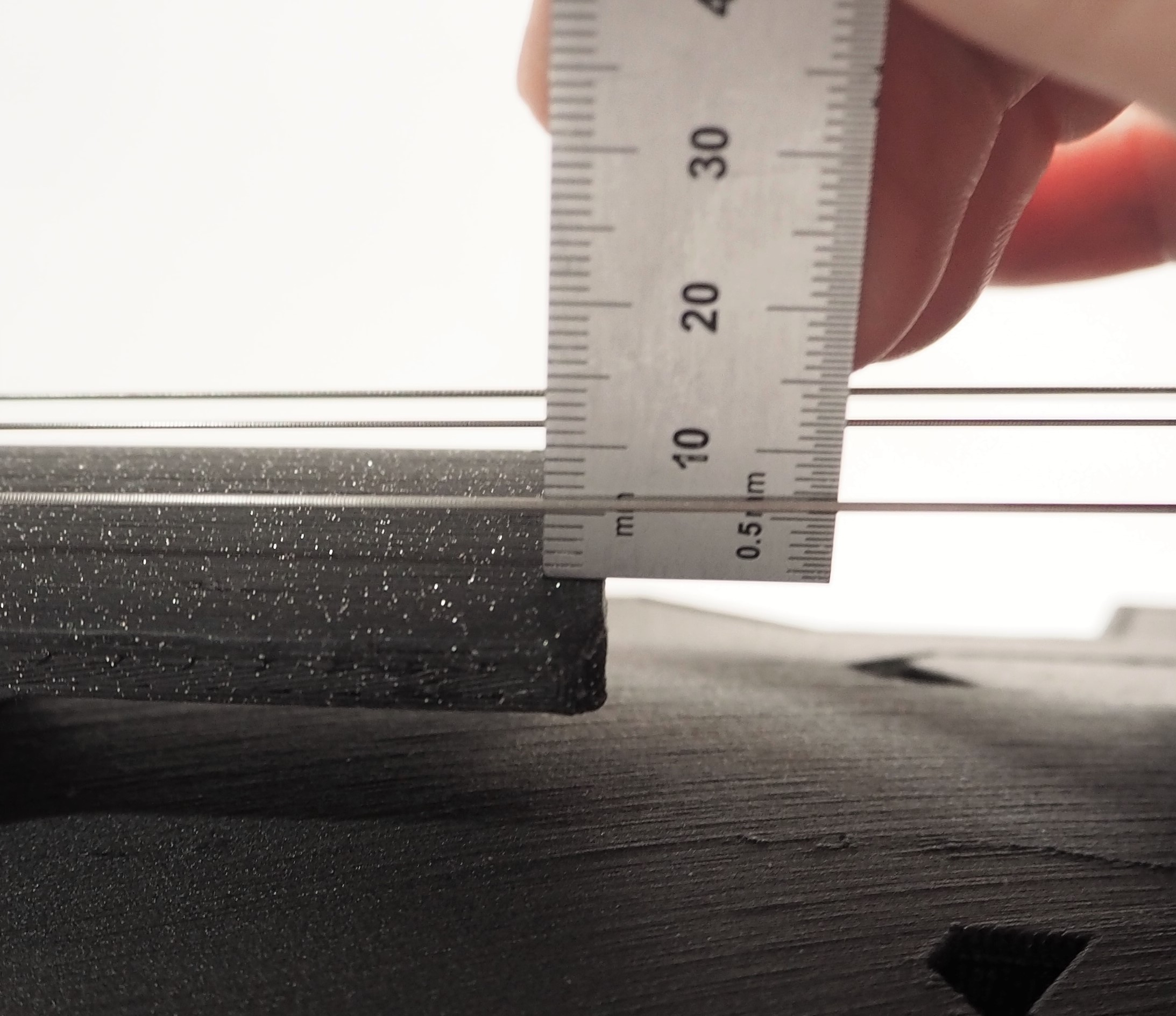
The G string is just about spot on at 5.5mm.
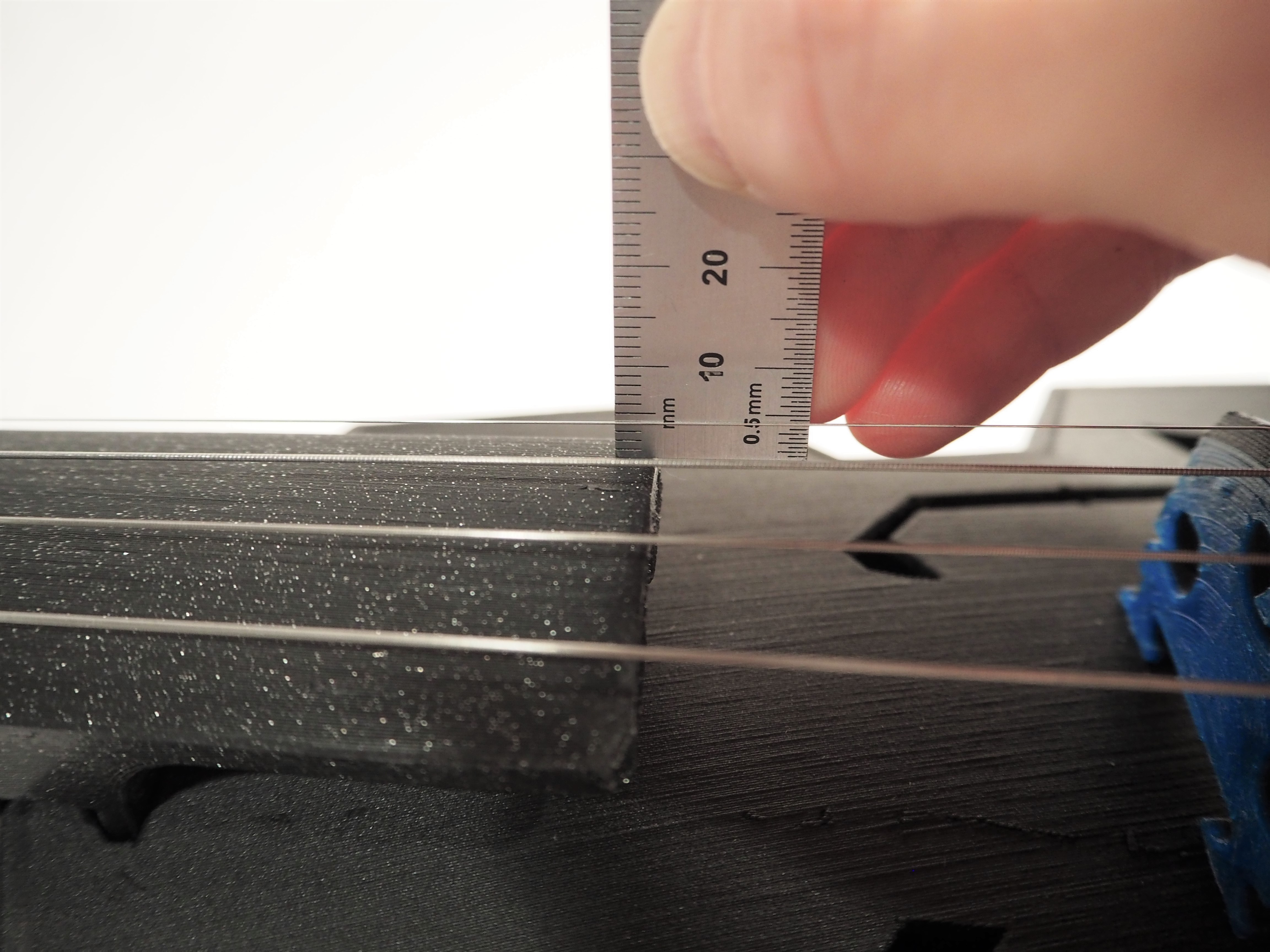
The E string here is at 4mm, a tad high, but I’ll leave it and check again in a week.
If you need to increase your string heights, don’t do anything yet. Give the instrument a few days to settle in and then measure again. In fact, I would say that if your values are within 1mm of nominal, just leave it and measure again in a few days.
Keep track of your string heights (at end of fingerboard) over time — it will give you some good information about how your fiddle is changing over time. All violins change some over time, but these plastic fiddles will change faster. How fast? We don’t know yet!
The V1 Modular Fiddle does not fit a traditional shoulder rest, but the V2 will fit most shoulder rests. V3 is even better!
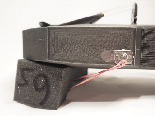
Another option for V1 or V2 is to fasten a sponge-type shoulder rest using a rubber band and an adhesive hook, as shown here.
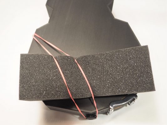
An adhesive hook can be applied to one side of the fiddle. Then you can use a rubber band from the endpin to hook to secure a foam sponge shoulder rest.
 You’ve done it! Thank you for building a Modular Fiddle. Please share photos of your fiddle. You can email them to me, or post them on the Google Group or in the Discord server, or just throw them on Instagram with the tag #ModularFiddle. Searching that tag is a good way to see what I’m up to as well.
Back to business. Once you’re tuned about to pitch, you’ll need to re-tune as needed as everything settles. Don’t expect the fiddle to stay in tune very well for a couple weeks.
If you are using geared uke tuners or geared pegs, your instrument should stay in tune quite well after the settling period.
Pro Tip: One observation related to the Grover 6-series tuners — they have a little bit of looser travel in them. You will stay in tune best if you tune high, and descent to the proper pitch. This means that bit of loose play will not cause your instrument to go flat. I believe this loose play is what causes most Modular Fiddles to go a bit flat over time.
If you continue to lose string tension, then try to figure out why. Are your string heights changing? Then perhaps it’s from deflection in the top plate (lowering string heights) or slow bending in the neck (increasing string heights). Usually it’s the tuners slipping that causes the instruments to fall out of tune, so tighten those tuners! If you are still not staying in tune, let me know – I’d be curious to talk about it. You can also post about it on the Discord server. There are folks there that know a lot.