
Product Design, Prototyping
Seizing Static Simulation for a Super Sized 3D Printed Sphere Stand
Feb
One of the most popular items in my Etsy store is a 3D printed sphere stand for polished rock and mineral spheres, but it is on the smaller side. Several reviewers mentioned that they would like a larger version. So let’s do it! In this post I’ll show you how I use simple static simulations to optimize my design of a larger 3D printed sphere stand.
Too Large or Large Enough?
First — how large does this stand need to be? Most of my spheres are 2 inches in diameter, and they don’t fit well on the smaller stand. So let’s at least fit 2″ spheres. But some folks have larger — let’s go for 3″ spheres! This stand will fit well on my 3D printer, but with an increase in diameter, the volume and mass increase proportional to the cube of this increase, so we will need to significantly strengthen the stand.
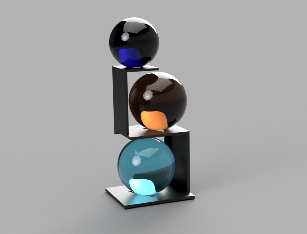
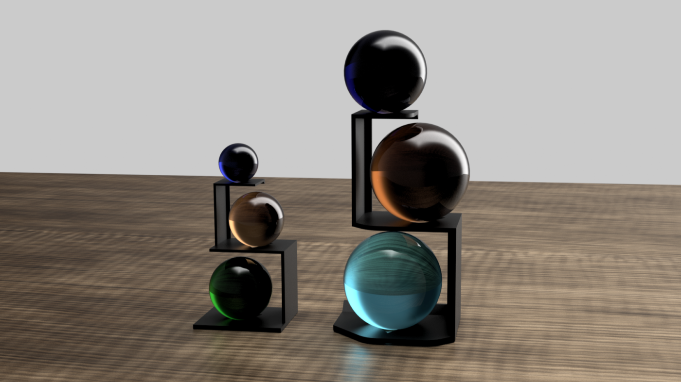
Before I get into the engineering details, I’ll model the stand and the spheres and adjust the design until everything fits aesthetically the way that I want. I want the spheres to be well positioned visually, and also positioned so that they do not put excess strain on the stand. This style of 3D printed sphere stand, because it does not have support on both sides of the sphere, is subject to a lot of stress.
Using Simulations to Check Stiffness
With a smaller stand, or a smaller product, I would simply print a prototype, load it up, and see how it performs. If it needs to be thicker I can adjust it and print it again. For this stand, though, it’s a three hour print using an expensive material (carbon fiber PLA), so I would like to validate the design before I print the first sample.
Fusion 360 makes it super easy to run a quick simulation! I also have the previous 3D printed sphere stand design, which I know is stiff enough, to use as a comparison.
Simulations are helpful, but they can be misleading, so it is very important to have a design that has been validated in the real world with which to compare.
A simple static load simulation using gravity and glass spheres tells me that the previous design has a maximum displacement of 0.5mm. I will be happy if we can get to within 2X of that value, given the increase in size of the stand and spheres.
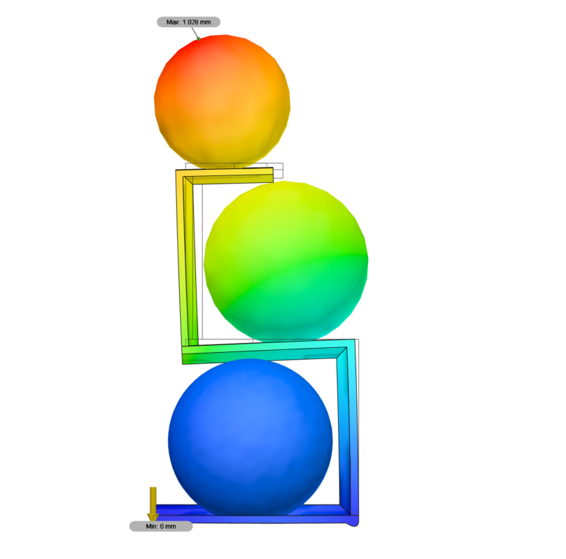
The first simulation of the new design shows us a maximum displacement of just over 1mm. That’s pretty good! Let’s take a look at the strain distribution to see if we can’t determine what is bending and where.
From the strain distribution (stress would work as well), we can see that the ‘beam’ with the most bending is that first vertical section of the stand. I don’t want to thicken the total cross section, but each beam has a thick section at the back of the stand to carry the bulk of the mechanical load. This way, a slim profile is presented to the viewer, but a thicker beam exists at the back to support the spheres. Let’s thicken this section on the lowest horizontal beam and the first vertical section.
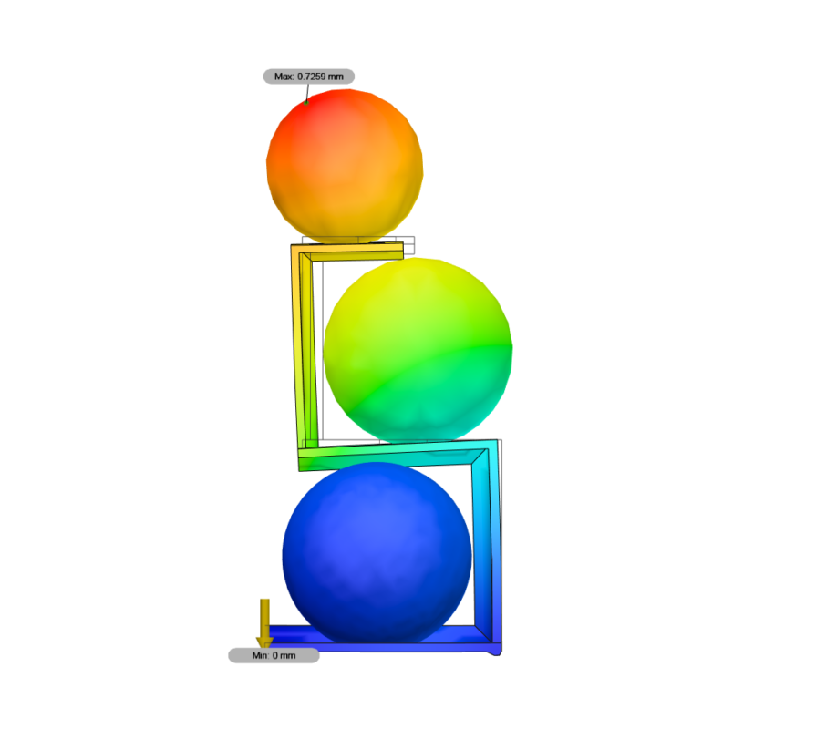
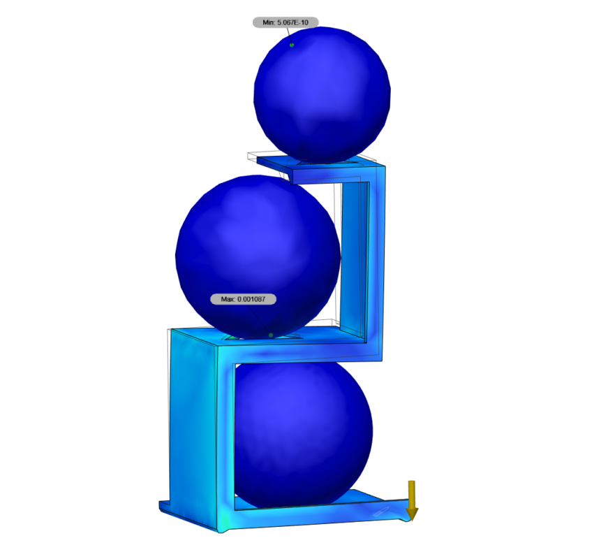
Great — thickening those sections brought our displacement down to .73mm. I’m happy with that, but I’m going to spend a bit of time to clean up some extra material and perhaps improve the way stress is distributed in the part by trimming the excess corners.
This is mostly for aesthetic reasons, but let’s run the simulation again for fun because it literally takes 10 seconds to run locally on my computer.
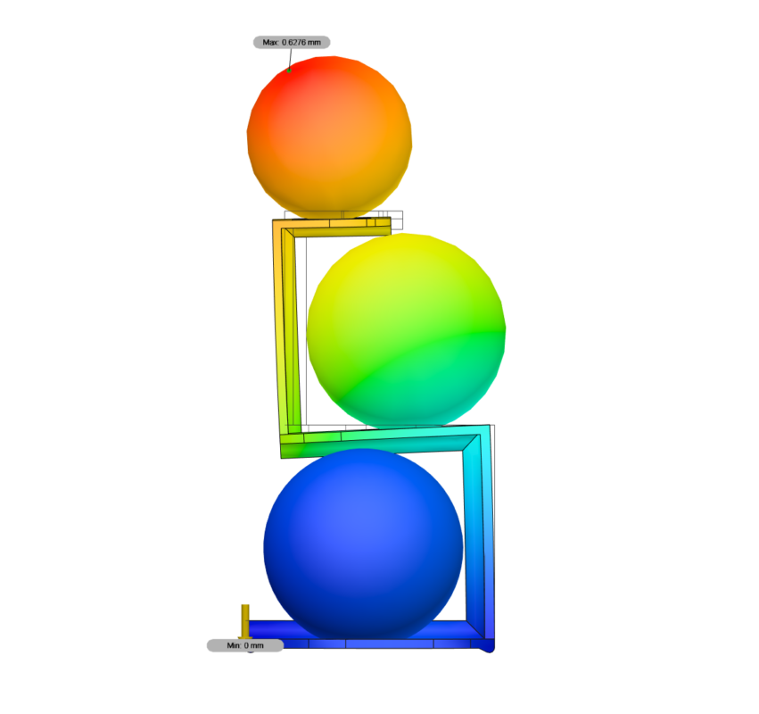
We got displacement down to 0.63mm! That’s a remarkable value considering the size and mass of these spheres.
Simulations Add Confidence
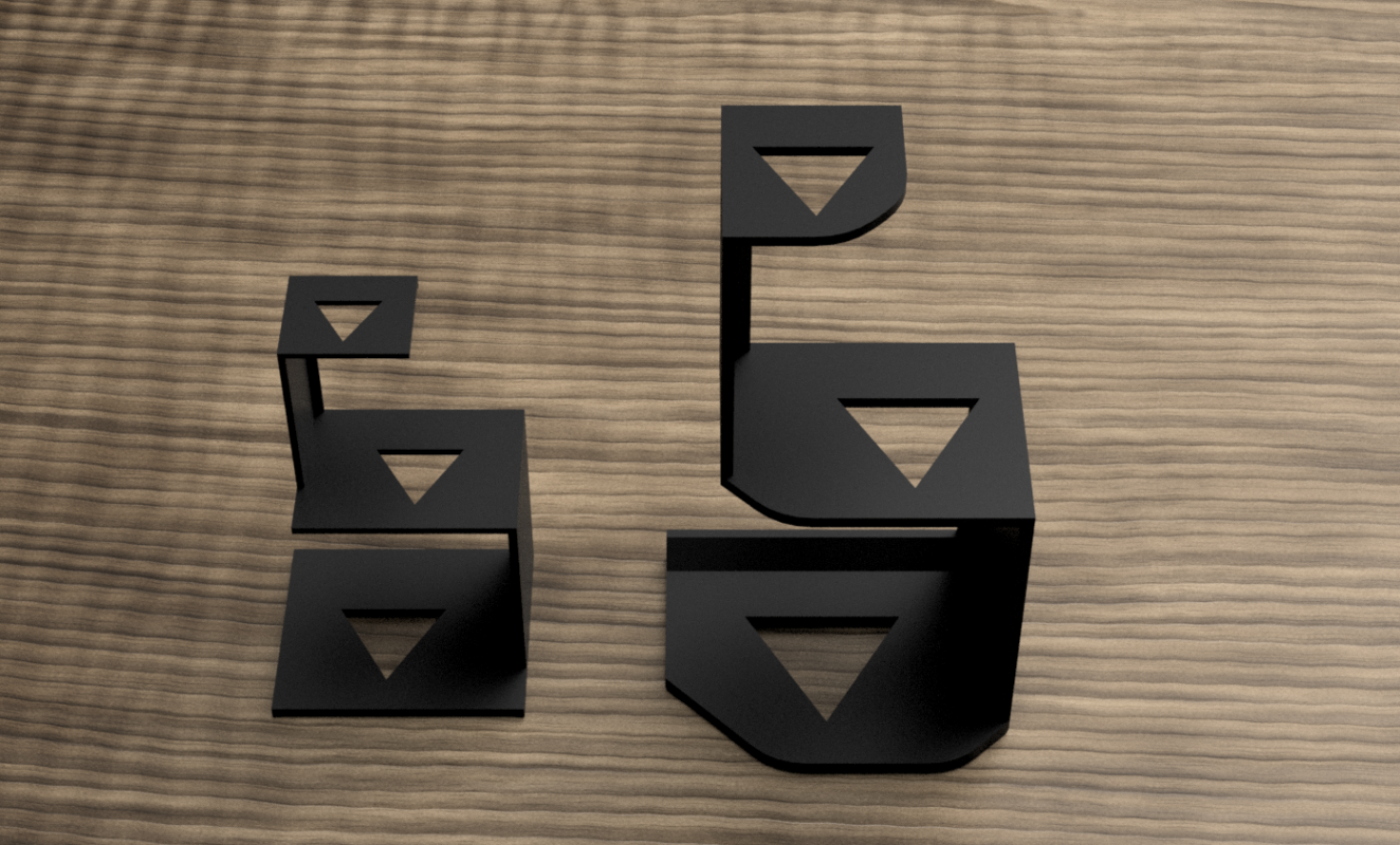
With these results, and most importantly looking at these results in comparison to the small 3D printed sphere stand results, I can move forward with confidence in my design. There will certainly be some tweaks down the road, but I am 100% confident that my first print will be good enough.
Sure enough…
Check out the listing on Etsy!